


Mist eliminators are devices used to remove liquid mists and aerosols, including oils, from air, gas, or vapor streams. They are commonly found in various industrial processes such as oil and gas refining, petrochemical, and chemical processing. There are different types of mist eliminators, each designed for specific applications. These devices primarily function by preventing the release of mist, oil vapors, or other substances such as acid vapors and hydrocarbons into the environment, thereby creating a clean and safe workspace. Another application of these mist eliminators is the protection of industrial equipment such as turbines, compressors, and others. Most gas streams in chemical or petrochemical processes contain mist or vapors of various liquids. These mists are formed by condensation, for example, after cooling processes, by liquid injection in absorption or gas cleaning processes, during chemical reactions, or due to lubricating oil vapors in the gas phase. These fine liquid droplets or vapors suspended in the gas stream can cause problems such as equipment corrosion, product contamination, fouling of heat exchangers or catalysts, and damage to instruments and machinery. Furthermore, when these droplets are released into the atmosphere, they can contribute to air pollution. Among the various types of equipment known as mist eliminators in industry are mesh pads, inertial or vane separators, cyclones, fiber filter elements, as well as electrostatic precipitators and other devices utilizing advanced technologies
In various industries, mist refers to a collection of extremely fine liquid droplets suspended in the air, which may result from industrial processes, liquid evaporation, spraying, or atomization of chemical substances. In fact, mists are microscopic droplets formed through atomization and condensation processes. Controlling and eliminating mist is of great importance in the oil and gas, chemical, and materials processing industries, as it can damage equipment, generate environmental pollutants, and pose health risks to employees . Some examples of industrially generated mist include acid mists, such as sulfuric acid mist, which can cause equipment corrosion and health-related problems. Other types of mist include oil mists, which are commonly produced during industrial operations such as machining, cooling, and lubrication of machinery and equipment. These oil mists can interfere with equipment performance and cause oil deposits on surfaces. Additionally, chemical and water mists are other types that may form in various processes
Three major mechanisms are primarily responsible for mist formation in industrial processes, including evaporation/condensation and atomization. The following describes how mist is formed by each of these mechanisms:
Mechanical Methods:
Physical shear forces can break up or atomize a liquid, forming an aerosol mist. Typically, mists generated by mechanical devices contain relatively larger particles, generally greater than 1 micron in size. In this mechanism, mist formation occurs mainly due to the mechanical energy applied to the fluid by rotating components, causing the liquid to disintegrate into droplets. For example, in drying and absorption towers of sulfuric acid plants, larger acid dust particles are formed as a result of the splashing and lateral displacement of liquid acid within the distributor and on the tower packing. These liquid sulfuric acid particles are then carried upward in the gas stream, and if their concentration is not reduced, they can cause downstream equipment corrosion and severe air pollution. Aerosol formation is also common in minimum quantity lubrication (MQL) processes, where a high-pressure air–oil mixture is directed toward the rotating tool or workpiece.
Cooling:
When a gas stream becomes saturated with vapor and is subjected to a temperature drop, the cooled vapor condenses within the gas stream, forming mist. The droplets formed as a result of cooling and vapor condensation are typically very small, usually submicron or smaller than 1 micron in diameter. Submicron mists may cause health and safety issues due to their fine size and ability to remain airborne for long periods.
Chemical Reactions:
In conditions where temperature and pressure are sufficient, the chemical reaction of two or more gases can generate aerosols and mists. For example, in metal smelting, coke production, or the reaction of sulfur trioxide (SO₃) with water vapor, submicron sulfuric acid mists are formed. In some chemical processes, the presence of mist during operation affects product purity and can reduce production rates due to catalyst fouling and process equipment corrosion, which in turn increases maintenance and operational costs.
According to one classification, industrial mists are generally divided into three categories: coarse mists, hybrid mists, and fine mists, as summarized in Table 1.
Fine mists, consisting of droplets smaller than 2 microns, are generally trapped using a fibrous coalescing bed, which in some filtration references is referred to as a candle filter

Various devices and equipment have been introduced to industry for the separation of mist droplets from gaseous fluids. Each of them is effective within a specific range of mist sizes and operates through different mechanisms such as filtration, inertia, centrifugal, and electrostatic. Mist eliminators can generally be categorized as impaction (inertia) filters, fibrous bed filters, mesh pads, electrostatic precipitators, and cyclones.
Electrostatic precipitators, or ESPs, are devices used to remove solid or liquid particles from exhaust gases in industrial processes. These devices utilize electrostatic force to capture suspended particles, dust, and mist on their electrode surfaces, thereby purifying the gas. This method is highly effective for removing dust, smoke, mist, and other fine particles from air or exhaust gases over a wide particle size range of approximately 0.001–100 µm. Figure 1 shows an example of an electrostatic precipitator.

Electrostatic precipitators mainly consist of a number of ionizing plates. As dusty air passes through these plates, collisions of electrons with air molecules produce positive ions, which then attach to the dust particles and give them a positive charge. The charged particles then enter a region filled with closely spaced parallel metal plates, which are alternately charged with positive and negative voltages, usually around 6000 volts. The positive plates repel the positively charged particles that have been attracted to the negative plates, keeping them on the negative surfaces. As the particles settle on the plates, the electrostatic forces are complemented by intermolecular forces, leading to dust accumulation. Figure 2 shows a schematic of the operation of an electrostatic precipitator.

As the dust layer accumulates on the electrode, the collection efficiency may decrease, especially if the electrode is inside a cylindrical tube. In addition, some dust has a very resistive surface and does not discharge onto the electrode but rather sticks to it. Heated or water-washed electrodes may solve this problem. Electrostatic precipitators are efficient collectors of very fine particles. The electrical energy consumed by an electrostatic precipitator can be significant, resulting in high operating costs. The particle removal efficiency of an electrostatic precipitator is calculated using the following formula:
A = total collection surface area of the collecting electrodes (m²)
Q = gas flow rate through the duct (m³/s)
Ud = drift velocity
The drift velocity is the velocity at which particles move toward the collecting electrode and can theoretically be calculated by equating the electrostatic force acting on a charged particle in the electric field to the drag force experienced by the particle while moving through the gas.
At the inlet of these devices, a pre-filter is mainly installed to capture larger particles and droplets. Additionally, downstream of the plates, a supplementary filter, such as activated carbon, is used to remove odors and much finer particles. Figure 3 shows an example of an ESP designed by Parker Company.

One of the most commonly used types of mist eliminators is the inertial type, which is designed to separate liquid droplets from a gas stream. These filters operate based on the mechanism of inertial impaction: liquid droplets, due to their greater inertia, are unable to follow the gas flow streamlines and consequently impact onto the surfaces of the filter elements.

These devices mainly provide a good balance between efficiency, pressure drop, and installation cost, and consist of a series of baffles, vanes, or plates through which the gas must flow. As shown in Figures 4 and 5, when the gas approaches the surface of the baffles or discs, the fluid streamlines spread around the baffles or discs. Ignoring the vortices formed around the plates, it can be assumed that the higher the flow velocity, the closer these streams approach the target. In this type of equipment, the vanes force the gas flow to move slowly between parallel plates that have directional changes. The surface of the plates acts as a target for droplet impaction and collection. The spacing between the baffles is mainly 5 to 75 mm, with an overall depth in the flow direction of 150 to 300 mm. A droplet can be captured by the baffles or discs in a vane-type dust collector through any of the three mechanisms: inertia, direct interception, and even diffusion. The way these mechanisms operate is shown in the figure 5.

Mainly, three types of configurations have been used for this model of filters: horizontal for vertical gas flow, vertical for horizontal gas flow, and inclined. The waves present on the baffles change the direction of the gas flow, but the inertia of the droplets causes them to move straight forward and collide with the baffles. By increasing the number of incorporated separation chambers, i.e., creating two-phase, three-phase, or four-phase separation, the collection efficiency can be improved. However, the optimal geometry depends on the type of eliminator (longitudinal, vertical, or inclined), which affects the collection and drainage of liquid droplets.
Theoretically, efficiency up to 100% is possible, but the practical efficiency is lower and limited by the designed droplet size. An optimal velocity is necessary to prevent re-entrainment of separated droplets into the gas flow. Larger droplets are better separated through impaction or inertia mechanisms; for smaller droplets, supplementary mechanisms may be required.
For a specific design of a dust eliminator, the cut-off droplet size is a complex function of the velocity. Figure 5 shows examples of mist eliminators installed in vertical and horizontal separator chambers. It shows a vane-type dust collector installed respectively in a vertical and horizontal separator.
Nowadays, vane-type dust eliminators are made from various materials, including polypropylene, fiberglass-reinforced polymer (FRP), polysulfone, and stainless steel, each with its own specific advantages and disadvantages. The choice of material has a direct impact on operations and maintenance requirements, as well as on the capital and operating costs associated with dust eliminators, especially under harsh conditions where high pressures, high temperatures, high acidity, and high liquid loading are applied.

The separation mechanism for gas–solid/liquid in mesh pad mist eliminators is inertia. Typically, mist eliminator pads, consisting of fibers or knitted meshes, can remove droplets from 1 to 5 microns, but the vessel containing them is relatively large because the fluid velocity must be reduced to prevent re-entrainment of liquid droplets. Droplet separation from a fluid can be achieved using metal or plastic meshes. The operating mechanism of this type is similar to that of fiber-bed separators, with the difference that these meshes are mainly used for larger droplet sizes.
Operating Principle of Mesh Pads
In the most general sense, these devices consist of a simple porous sheet made of metal or plastic wire that retains liquid droplets carried by the gas phase. The separation process in a mesh-pad mist eliminator mainly involves three stages. In the first stage, under the influence of the inertial mechanism, liquid droplets are deposited on the surface of the wires. In fact, as the gas phase passes alongside or around the wires in the mesh panel, the flow streamlines are deflected, but the kinetic energy of the liquid droplets associated with the gas flow may be too high to follow the gas streamline, causing them to collide with the wires. The second stage in the separation process is the coalescence of the droplets upon contacting the surface of the wires. In the third stage, the droplets are removed from the pad. In installations with vertical flow, the collected liquid drains as large droplets from the upstream surface of the mesh pad under gravitational force.
For maximum efficiency, the face velocity (i.e. the gas flow velocity across the surface of a filter) must fall within a specific range. If the velocity is too high, the separated liquid will be re-entrained into the system. If the velocity is too low, mist droplets will pass through the mesh without collision and coalescence. Therefore, according to references, the gas flow velocity must be considered within an operating range between 30% and 75% of the maximum allowable velocity determined by the following equation. Under this condition, mesh pads will have reasonable performance.
Vm= K[(D-d)/d]0.5
Where:
Vm: maximum allowable velocity (m/s),
d: density of gas/air,
D: density of liquid,
K: a constant, usually 0. 107.
Wire mesh mist eliminators are usually installed in upward vertical gas flow, although horizontal flows are used in some specialized applications. In a horizontal flow, the designer must be careful, because liquid droplets captured at higher elevations of a vertical mesh may drain downward at an angle as they are driven through the mesh, resulting in re-entrainment. Another point regarding this type of equipment is that the pressure drop through a wire mesh unit is a combination of “dry” pressure drop due to gas flow, plus “wet” pressure drop caused by liquid retention. The wet pressure drop is a function of the liquid loading as well as the mesh geometry.
One point to consider is that a mesh-type or baffle-type mist eliminator mainly provides low pressure drop. To ensure that the unit operates at design capacity with high mist removal efficiency, the gas phase flow pattern must be uniform across the element. When size limitations exist inside the process vessel, an integrated baffle plate can be installed at the downstream side of the wire mesh element to act as a vapor distributor.
However, mesh mist eliminators and vane-type separators are widely used in many industrial plants. Despite their widespread use, their application is limited in some processes. Many experimental studies and mechanical models have been published to improve the performance of mesh and vane-type mist eliminators. However, although these types of mist eliminators can generally be used in most distillation and absorption columns, they cannot be used in operations involving acidic dust, fine mist generated by condensation of liquid from saturated vapor, oily dust from compressed gases, etc., due to their poor removal efficiency.
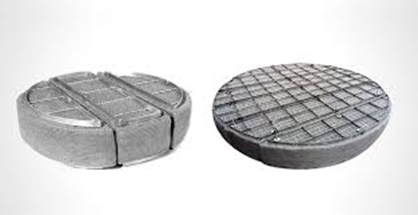
This type of equipment is mainly used to capture very fine liquid mist, approximately smaller than 2 µm. The structure of fiber-bed mist eliminators typically consists of a cylindrical vessel that includes one or several fibrous filter elements which separate mist droplets through the coalescing mechanism. Figure 8 shows a schematic of this type of equipment. Fiber-bed mist eliminators, or candle filters, use different mechanisms to remove mist droplets, which are described below:

In fiber-bed mist eliminators, there are mainly three essential stages for mist droplet separation, including particle capture on the fiber bed through filtration mechanisms, droplet coalescence, and finally drainage.
Particle capture process
The primary mechanisms for capturing mist particles on the fiber bed, similar to meshes and impaction-type filters previously mentioned, include inertia, interception, and diffusion. The inertial mechanism can remove a mist particle from the gas stream when it collides with a fiber. The larger the particle, the greater its mass. If the gas velocity is sufficiently high, the mass of the particle moving in the gas will have enough momentum to collide with the fiber instead of following the gas flow path, and it will adhere due to weak van der Waals forces.
Another mechanism, direct interception, occurs in fibrous filters when mist particles in the gas or air stream directly contact the fiber surface without deviating from the flow path. Unlike interception, inertial impaction causes particles to deviate from the stream due to their inertia.
Finally, the diffusion mechanism applies to smaller particles, which are captured due to Brownian motion, meaning random molecular movements. This molecular motion causes collisions between gas molecules and suspended mist particles. As mist particles are struck by gas molecules, momentum exchange causes a random “zigzag” motion of the particles. Since the main purpose of using this type of fiber-bed eliminator is to capture very fine mist droplets, Brownian motion is the dominant mechanism for submicron droplets in fiber mist eliminators (as shown in Figure 9).
In the diffusion mechanism, because bulk gas momentum is not involved, the collection efficiency does not improve for larger droplets, higher gas velocities, higher liquid density, or lower gas viscosity, as it does in vane and mesh separators. Instead, efficiency increases with higher temperature, longer residence time in the fiber bed, and closer fiber packing, and decreases as droplet size increases.
Coalescence and Drainage
After mist droplets are captured on the fiber surface, they accumulate and merge through the coalescence process, forming liquid films that move along the fibers under gas flow. The collected liquid is then drained by gravity, often aided by a drainage layer at the downstream side of the filter element. Figure 10 illustrates droplet coalescence and liquid drainage within an acid mist eliminator element.

This type of mist eliminator primarily uses fibers with extremely small diameters—typically less than 0.02 mm—to capture very fine droplets. Because the filter element bed is composed of densely packed fibers, gravity-driven drainage within the element is limited. As a result, most of the liquid is eventually forced through the microfibers and discharged at the downstream side. The surface area of a microfiber mist eliminator can be 3 to 150 times greater than that of a wire mesh unit of the same volume. The filter medium is typically made from glass, polyester, polypropylene, or Teflon fibers, and housed within a vessel constructed from metal, fiberglass-reinforced plastic, or polypropylene.
Fiber-type mist eliminators (often designed as long vertical candle elements suspended inside a suitable chamber) generally share a similar overall configuration. However, the key difference lies in the nature of the fibers used within these elements.
Fairs and Brink, two leading researchers in this field, expressed differing views regarding the desired fiber properties. Fairs emphasized the importance of hydrophobic fibers, while Brink considered this requirement unnecessary. Fairs’ argument was based on observations that the filtration efficiency of fiber-type mist eliminators was often significantly lower than theoretical predictions and that the elements tended to become saturated (waterlogged) due to liquid accumulating on the fiber surfaces. In contrast, mist eliminators constructed with hydrophobic fibers achieved the high theoretical efficiencies and avoided bed saturation.
This difference in performance was attributed to the contrasting ways in which droplets collect on hydrophilic versus hydrophobic fibers. When unmodified hydrophilic glass fibers become wet, their effective diameter increases, which reduces filtration efficiency. This loss of performance does not occur with silicone-coated, hydrophobic glass fibers.
Cyclone Mist Eliminators
Two main types of cyclone mist eliminators exist: tangential and axial.
Both rely on centrifugal separation as the dominant mechanism. Tangential cyclones are usually employed as stand-alone dust or mist collectors, while axial cyclones are often installed as internal devices within vessels.
The gas–liquid cyclone principle is similar to that of gas–solid cyclones, but with some unique challenges and advantages due to the liquid phase. Unlike solid particles, liquid droplets are larger and non-porous, which simplifies their separation and minimizes clogging risk.
For separating larger droplets, cyclones are advantageous due to their low maintenance requirements and high performance compared to other types of mist eliminators.
Combined Mist Eliminators
To combine the advantages of different types, hybrid mist eliminators have been developed.
Dual-stage units—such as vane separators installed upstream or downstream of mesh pads—can significantly enhance performance for specific process conditions.
Amistco introduced a combined mist eliminator integrating both mesh and vane elements, as illustrated in Figure 11.

Membrane Mist Eliminators
The application of ceramic membrane technology as a gas–liquid separator is a strategic innovation. Due to their high selectivity, ceramic membranes can capture droplets as small as 0.1 µm.
They are also washable and regenerable, enabling continuous operation and longer service life.
From an economic standpoint, membrane technology reduces downtime losses common in conventional systems, providing a more stable and sustainable process.
In 2009, Wenten proposed ceramic membrane systems for condensate separation from gas streams.
In practical applications, membranes are assembled into modules, each containing 19 ceramic tubes, housed in a stainless-steel vessel rated up to 40 bar.
Multiple modules are mounted in parallel on a skid, with condensate collection piping.
For optimal operation, one module remains in back-flush or standby mode, automatically switching when another module experiences performance decline due to fouling.

Parameters Affecting Mist Eliminator Selection
Several key factors must be considered when selecting a mist eliminator:
Particle Size
One of the key parameters in selecting the type of mist eliminator is the size of the mist droplets. As a general rule often applied in choosing a mist pad, the predicted droplet size is considered. First, bubbles generated by mechanical processes, such as boiling, two-phase flows, seal leakage, surface condensation, etc., usually produce droplets larger than 20 µm. Second, bubbles resulting from chemical processes, such as reactions, condensation, and similar phenomena, typically generate submicron droplets. Therefore, to collect chemical droplets using a mist eliminator, these droplets must be forced to coalesce. Droplet collisions promote coalescence and increase the droplet size. Larger droplets, which have greater inertia, are usually separated from the flow using vane-type separators or mesh pads, whereas finer droplets are removed through Brownian diffusion and direct interception mechanisms.
Performance Evaluation of Mesh and Fiber Mist Eliminators
Key elements in evaluating the performance of fiber or mesh mist eliminators include particle removal efficiency, particle re-entrainment, pressure drop, corrosion resistance, and chemical compatibility. When comparing mist eliminator performance, it is appropriate to consider efficiency based on the percentage of particles collected, categorized by particle size rather than by weight. This distinction is important because many operational issues, such as cloudiness, are primarily caused by smaller particles. Since a 0.5 µm particle weighs only one-thousandth of a 5 µm particle, some mist eliminators can easily achieve 99% or higher efficiency by total weight without collecting the finest particles.
The mechanical performance of a mist eliminator is typically assessed using two curves: collection efficiency versus particle size and pressure drop versus vapor load. For high-efficiency operation, a mist eliminator should have fibers or mesh with a high surface-to-volume ratio.
Table 2 provides a comparison of different types of mist eliminator.

Acid mist or dust is generated in drying and absorption towers of sulfuric acid plants as a result of liquid acid splashing and shearing in the acid distributor. These fine droplets become entrained in the upward gas stream. The collection of fine acid particles results from the reaction of sulfur trioxide (SO₃) with any moisture present, and from condensation of acid from the vapor phase.
These acidic aerosols can corrode blowers, ducts, and heat exchangers, damage catalysts, and cause atmospheric pollution.
The fiber bed mist eliminator used in sulfuric acid service consists of a thick element made of acid-resistant fiberglass fibers housed in a containment vessel. Gas streams containing mist particles pass horizontally through the fibrous bed. The droplets are captured on individual fibers, where they coalesce to form continuous liquid films and larger droplets that migrate through the bed under the influence of the gas flow. The collected liquid is then drained from the downstream surface.
Figure 13 shows a sample of commercial fiber bed elements designed for acid mist removal.
Oil Mist Separators (Oil Mist Eliminators)
The release of airborne lubricants poses a serious health risk to personnel in the metalworking industry. The primary components of lubricants are base oils and additives formulated to meet process requirements. These oils may be mineral, synthetic, or of biological origin. Lubricants are used both as water-based emulsions and as straight oils.
Harsh operating conditions often lead to the formation and release of significant amounts of lubricant aerosols and vapors into the workplace atmosphere.
Fiber filters are commonly used in industrial drying systems for both pollution control and sampling applications. However, the re-evaporation of separated lubricants from loaded fiber filters can increase vapor emissions.
Oil mist separators (or oil mist eliminators) are devices designed to remove oil mist from air or gas streams. These systems are widely used in industrial processes that generate oil mist, such as machining, metalworking, and lubrication operations. Oil mist formation is also unavoidable during the operation of turbines, engines, and compressors. For example, turbine bearings are lubricated with oil to ensure smooth operation. Friction between the shaft and bearings generates heat, leading to the formation of extremely fine oil mist droplets. The oil mist separator prevents these droplets from escaping into the atmosphere, where they could form oily deposits on equipment and buildings, cause environmental contamination, machine failures, and health hazards for workers. Figure 14 illustrates a schematic of FRANKE-Filter’s oil mist separator.

These units mainly consist of a side-channel blower and a filter housing containing multiple filter elements. The side-channel blower generates a negative pressure inside the housing, drawing oil-laden air into the unit. The contaminated air passes through the filter elements, where oil droplets are captured, and clean air exits the housing. The separated oil drains down along the fiber surfaces into a collection sump at the bottom of the unit. Figure 15 shows schematic representations of an oil mist separator structure and operation

The operation of these filter elements is based on the coalescence mechanism. As the oil mist-laden air passes through the fibrous medium, the microfibers capture fine oil droplets. These droplets gradually merge through the coalescence process to form larger drops that can no longer be carried by the gas stream. Finally, the enlarged droplets drain downward under gravity to the collection section.
One of the most effective methods for eliminating oil mist is the use of fibrous filters.
In recent years, many researchers have investigated gas–liquid coalescing filtration with respect to filter medium composition, structural parameters, wettability, and operating conditions.
Surface Modification for Adjusting Filter Medium Wettability
Fibrous filters are widely applied for oil mist removal from air and gas streams in industrial applications. The wettability of the filter medium strongly influences droplet–fiber interactions, liquid transport, and distribution within the medium — which in turn affects both filtration efficiency and pressure drop.
Although surface modification has been employed to alter the wettability of filter media and enhance performance, its impact on the mechanism of liquid transport and overall filtration behavior remains under study.
In a study conducted by Chang et al., the performance of fibrous filters in removing oil mist from industrial gas streams was investigated. The focus was on modifying the surface wettability of the filter media using a fluorocarbon copolymer spray treatment, and evaluating its effect on liquid transport and filtration performance.
The effects of treated surface ratio, spray duration, and composite filter media configuration were examined experimentally. Results showed that increasing the fraction of treated surface area changed the surface property from oleophilic to oleophobic, which reduced the pressure drop spike and enhanced filtration efficiency. The optimized spray-treated medium achieved the highest quality factor, being 2–3 times greater than that of the untreated medium.
Effect of Operating Conditions
The operating conditions of oil mist filters, along with the characteristics of the filter medium, are determining factors for the development of separation efficiency and pressure drop during filter operation. Experimental studies to determine changes in the clean gas concentration in oil mist filters with different medium characteristics and considering the oil transport mechanisms and their dependence on filter operating conditions were conducted by Penner and colleagues. These experiments were performed using two types of fiberglass media: one oleophilic (oil-absorbing) and the other oleophobic (oil-repelling). The effects of air flow velocity over the filter surface and the oil loading rate were investigated for both types of media. Additionally, the effect of medium thickness was examined by varying the number of layers.
The results indicated that the overall separation efficiency of the filter can be related to oil transport mechanisms similar to the Film-and-Channel model proposed by Kampa and colleagues in 2004, which was based on measurements of liquid distribution and transport in multilayer media. Liquid transport among the medium interfaces and within the media generates channel and jump pressure drops. The jump pressure drop and channel pressure drop are the two characteristic features for both wetting and non-wetting media, where the jump pressure drop is proportional to the static pressure of the passing oil or air, and the channel pressure drop is related to the medium thickness.
Reducing the flow velocity led to increased penetration (reduced efficiency) under conditions where liquid channels were formed in both types of media. Increasing the oil loading rate had a similar effect on penetration as flow velocity, although the intensity of this effect was not as significant as the reduction in air flow velocity. Increasing filter thickness by adding medium layers also caused an increase in penetration in the channel stage. The formation of an oil film on the filter surface reduced penetration (increased efficiency).
The emission of various types of mist—such as acidic, oily, aqueous, or chemical aerosols—within air or gas streams can often lead to machinery damage, corrosion, increased energy consumption, and air pollution. Therefore, the removal of mists from process and exhaust gases is of significant importance in many industrial applications.
A variety of methods and equipment have been developed for mist elimination, several of which have been reviewed in this study. In general, the use of mist eliminators for separating liquid droplets from industrial gas streams can be categorized into two main purposes: process gas purification (as a process requirement) and exhaust gas cleaning (for environmental protection).
Overall, fiber-bed mist eliminators—when properly designed and matched with specific operating conditions—can provide highly efficient removal of fine liquid droplets through the combination of multiple separation mechanisms. The selection of a suitable mist eliminator depends on several key factors, including gas flow capacity, liquid loading, cost, required efficiency, gas composition, and droplet size distribution. Furthermore, the internal configuration and installation layout of these units play a critical role in achieving optimal mist removal performance.
[1] Purchas, D., & Sutherland, K. (Eds.). (2002). Handbook of filter media. Elsevier.
[2]Mead-Hunter, R., King, A. J., & Mullins, B. J. (2014). Aerosol-mist coalescing filters–A review. Separation and Purification Technology, 133, 484-506.
[3] Fiber bed mist eliminator refresher: theoretical fundamentals vs. real world
[4] Wenten, I., & Chandranegara, A. S. (2008). Improving Mist Eliminator Performance in Gas-Liquid Separators.
[5] Stewart, M., & Arnold, K. (2008). Gas-liquid and Liquid-liquid Separators. Gulf Professional Publishing
[6] https://franke-filter.com/
[7] Weiner, R., & Matthews, R. (Eds.). (2003). Environmental engineering. Elsevier.
[8] J A Brink (1959) ‘New fiber mist eliminator’, Chemical Engineering, 66,
[9] G L Fairs (1964) ‘Hydrophobic fibre filters’, Gas Purification Processes (ed. GNonhebel), Geo Newnes Ltd, London, pp. 711-15
[10] AMISTCO. “Mesh & Vane Mist Eliminators for Optimal Removal of a Wide Range of Liquid Droplets from Gas Streams”. 2004
[11] Chang, C., Lyu, Q., Ding, Y., & Ji, Z. (2024). Investigation of oil mist filtration performance of surface modified coalescence filters with asymmetric wettability. Separation and Purification Technology, 331, 125465.
[12] El-Dessouky, H. T. (2002). Fundamentals of Salt Water Desalination. Elsevier.
[13] Penner, T., Meyer, J., Kasper, G., & Dittler, A. (2019). Impact of operating conditions on the evolution of droplet penetration in oil mist filters. Separation and Purification Technology, 211, 697-703.
Author: Forough Khalili

 Save the post
 Projects: