


The purified gas from the acid gas removal unit is fed to the gas dryer unit to reach the water dew point required for transmission in the pipeline, which is usually 7 pounds of water per million cubic feet. In colder regions, the water dew point specification can be lower to prevent hydrate formation in the pipeline, prevent pipeline corrosion, and eliminate line blockages caused by hydrate formation. The two main types of dehydration equipment used today are liquid and solid dryers. Each type of dryer has its advantages and disadvantages. These two types of dryers dry almost all of the natural gas transported through transmission lines.
In the case of solid desiccant, the degradation of the adsorbent bed due to foreign substances such as glycol, amine, lubricating oil, corrosion inhibitors, and solids occurs by covering and blocking the pores of the adsorbent, preventing access to its large internal surface area. The use of a filtration system upstream of the adsorbent prevents the degradation of the bed and reduces its permeability by effectively removing solids and liquids. Also, placing a dry gas filter downstream of the bed protects downstream equipment such as compressors, cold boxes, catalytic beds, etc.
Durable and highly efficient polyester filter media with high wear and corrosion resistance and excellent dimensional stability ensure that the filter cartridges meet the requirements of the most demanding applications.
The natural gas to be transported through pipelines must have specific characteristics. In addition to specifications for delivery pressure, rate, and possibly temperature, other specifications include maximum water content (water dew point), maximum distillable hydrocarbon content (hydrocarbon dew point), allowable concentrations of contaminants such as H2S, CO2 mercaptans, minimum heating value, and cleanliness (allowable solids content). Additionally, if acid gases are removed using the amine method, the gas will be saturated with water and will need to be dried before entering the pipeline.
For natural gas recovery, the deethanizer or demethanizer column must operate at low temperatures. This requires removing sufficient water to prevent hydrate formation in the columns. If only propane recovery is desired, the column will operate at a warmer temperature of about 60°F. In this case, the use of a triethylene glycol (TEG) drying system may be sufficient. Depending on the plant capacity and the amount of drying required, there are various methods of drying, including glycol drying and drying with solid adsorbents (such as molecular sieves, silica gel, or activated alumina). A glycol unit is smaller and less expensive than a molecular sieve unit and is more suitable for offshore designs. However, if ethane recovery is required, then molecular sieve drying is essential.
The requirements of a dehydration unit are:
This article focuses on the principles of the process for water removal and the selection of the required filtration equipment.
The term “dehydration” means the removal of water vapor. All natural gas that has passed through separators still contains some water vapor. Water vapor is probably the most common undesirable impurity found in untreated natural gas. The primary reason for removing water vapor from natural gas is that water vapor condenses into liquid water at low temperatures and/or high pressures. In particular, water content can affect long-distance natural gas transportation for the following reasons:
Thus, the dehydration process helps to dry the natural gas, removes water from the natural gas, prevents the formation of gas hydrates and fouling of downstream sensitive components, reduces corrosion, maximizes pipeline and process efficiency, and protects water-sensitive catalysts in refinery processes.
The solubility of water in natural gas increases with increasing temperature and decreases with decreasing pressure. The presence of salt in the liquid water reduces the water content of the gas. The water content of untreated natural gas is typically in the range of a few hundred pounds of water per million standard cubic feet of gas (lbm/MMscf); whereas gas pipelines typically require water content in the range of 6 to 8 pounds per million standard cubic feet, and even lower for pipelines in deep water.
The water content of natural gas is indirectly determined by the dew point, which is defined as the temperature at which natural gas is saturated with water vapor at a given pressure. At the dew point, natural gas is in equilibrium with liquid water; any decrease in temperature or increase in pressure causes the water vapor to begin to condense. The difference between the dew point temperature of a water-saturated gas stream and the same stream after drying is called the “dew-point depression.”
Dehydration systems in the natural gas industry are generally categorized into six main types:
(a) Direct cooling,
(b) Compression followed by cooling,
(c) Chemical dehydration,
(d) Membrane dehydration,
(e) Absorption, and
(f) Adsorption.
The first four methods often do not achieve the low water content required for pipeline injection. Consequently, additional drying using absorption or adsorption is typically necessary.
Absorption is a process where water vapor is removed from natural gas by passing the gas in reverse through specific liquids designed to attract and absorb water. In this process, water vapor within the gas bubbles is trapped and carried away by the liquid.
Adsorption, on the other hand, involves passing the gas through a bed of granular solids that have a high affinity for water. The water adheres to the surface of the solid particles. The vessel facilitating the adsorption process is commonly referred to as a “contactor” or “sorber.” The liquid or solid used to absorb water in this setup is called a “desiccant.”
Choosing the appropriate dehydration method depends on various factors, including:
The ability of natural gas to retain water vapor diminishes as the temperature decreases at constant pressure. During the cooling process, excess water vapor condenses into liquid form and is subsequently removed from the system. The natural gas, now containing less water vapor, exits the cooling unit. However, the gas remains at its water dew point unless the temperature is raised again or the pressure is reduced.
This method is generally employed for gases with a high initial moisture content or when rapid and efficient separation is required. While economical in some cases, cooling is often best used in combination with other drying processes.
Gas compressors can function as partial dryers. In this method, natural gas is first compressed. As compression occurs:
At higher pressures, the reduced capacity for water vapor brings the gas closer to its saturation point. After compression, the gas is cooled, causing water vapor to condense into liquid form. This liquid, comprising water droplets, is separated from the gas and removed from the system. The cooling is typically achieved using heat exchangers, and the cooled gas is passed through a separator to remove the condensed water droplets. Gravity or cyclonic separators are commonly used for this purpose, effectively separating liquid water from the gas stream.
Ethylene glycol is often injected during the gas cooling stage at refineries. This not only aids in drying the gas but also facilitates the recovery of liquid hydrocarbons, functioning similarly to low-temperature separators.
This method relies on materials such as calcium chloride or lithium chloride, which absorb moisture through chemical reactions. Upon absorbing moisture, these materials are transformed into hydrated salts that can either be recycled or disposed of. While its use is limited to specific applications, this method can be highly effective in certain cases.
Membrane dehydration uses semipermeable membranes to separate water vapor from natural gas. These membranes allow water vapor to pass through easily while retaining other gases, such as methane and ethane, on the opposite side. As a relatively new method, membrane dehydration is gaining traction due to its simplicity, reduced need for absorbent material regeneration, and the use of more straightforward equipment.
Adsorption refers to the ability of a material to retain gases or liquids on its surface. In the adsorption dehydration process, water vapor in the gas is attracted to and concentrated on the surface of solid desiccants, where it is held by forces resulting from residual capacitance. Solid desiccants are characterized by their exceptionally large surface areas per unit weight, allowing them to effectively utilize these surface forces for dehydration.
The most commonly used solid adsorbents include silica, alumina, and specific silicates known as molecular sieves. Dehydration units employing solid desiccants can remove nearly all water content from natural gas. Owing to their superior dehydration capacity, solid desiccants are particularly effective in applications requiring higher efficiency.
Figure 1 illustrates a typical solid desiccant dehydration unit. Before entering the absorber, the wet inlet gas must be filtered to eliminate solid and liquid contaminants. During the dehydration process, the filtered gas flows vertically downward through an absorber containing a desiccant bed. This downward flow arrangement minimizes disturbances in the bed caused by the high velocity of the gas during adsorption. The dried gas exits the bottom of the tower and is ready for further processing or sale.
Most adsorption systems are equipped with two or more absorption towers, enabling continuous operation by regenerating one tower while the other(s) remain active. When one absorber is in the drying phase, the other is regenerated using a hot stream of gas from a heater. The required heat for regeneration can be supplied through various means, including direct heaters (hot gas), indirect heaters (hot oil), or steam.
During regeneration, the reducing gas typically flows vertically from the bottom to the top of the bed. This ensures complete regeneration of the lower section of the bed, which is the last area to come into contact with the gas being dried.

Before entering the adsorbent bed (e.g., molecular sieves), natural gas must be thoroughly cleaned of solid and liquid contaminants. These impurities must be removed to avoid:
Free water and hydrocarbons can also lead to breaking and pulverizing of the adsorbent material. During the regeneration process, hydrocarbons may burn on the adsorbent grains, progressively diminishing their moisture removal capacity. To address these challenges, gas filtration is typically divided into two primary stages:
This stage targets the removal of solid particles suspended in the gas stream. These particles may originate from pipelines, equipment corrosion, or environmental contaminants. The primary goal is to eliminate particles larger than a specific size to prevent damage to downstream equipment and clogging of the adsorbent bed.
The second stage focuses on eliminating liquid particles, including water and liquid hydrocarbons. If these liquids reach the adsorbent bed, they can:
Coalescer filters are utilized for this purpose. These specialized filters aggregate dispersed liquids into larger droplets, which are easily separated from the gas stream using gravity or other mechanisms. Coalescers are particularly effective for removing water and liquid hydrocarbons from the gas (for more details, refer to How Coalescer Filters Work).
The filtration system typically comprises:
These filters are available in various designs, including vertical and horizontal configurations (for more details, refer to Inlet Gas Filtration in Gas Sweetening Processes).

Over time, molecular sieves release fine desiccant particles, which are abrasive and can damage downstream processes and equipment. These particles can cause several issues:
To mitigate these issues, high-efficiency particulate filters are recommended to capture fine particles before they reach subsequent stages. Filtration systems are integral to every natural gas dehydration process using desiccants.
As each tower undergoes cyclical temperature fluctuations, some adsorbent beads inevitably break over time, creating dust and fine particles. These solids can disrupt downstream operations and the gas recovery cycle. To address this, mechanical filters should be installed at the outlet of the gas drying unit and before the gas cold box.
Dry gas filters (also known as gas particle or dust filters) are designed to remove solid contaminants from natural gas when no liquid is present. These filters use high-performance synthetic fiber cartridges to effectively filter small to medium amounts of solids, protecting critical pipeline equipment and maintaining optimal performance.
Key Applications of Dry Gas Filters
Contaminants Filtered by Dry Gas Filters
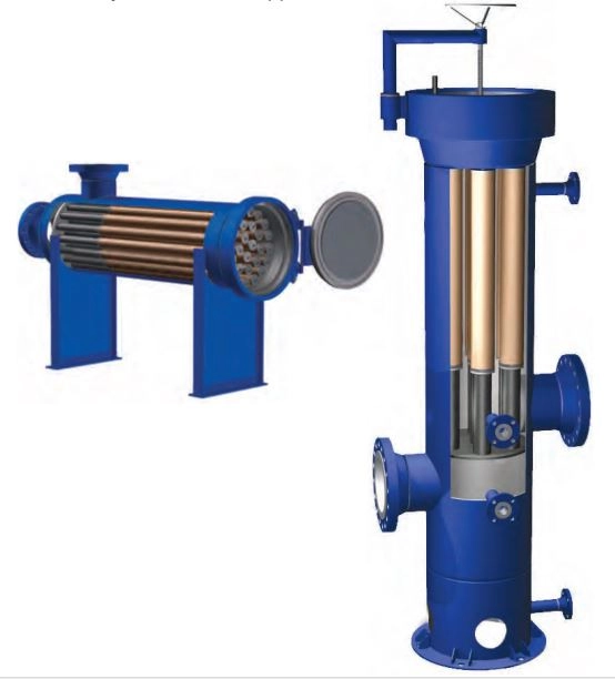
Dry gas filters are available in vertical or horizontal configurations (Figure 3) and a wide range of sizes, offering flexibility to meet diverse pipeline and industrial processing requirements.
Sometimes a pot strainer is placed after the molecular filters and before entering the next stage (Figure 4). A pot strainer with a higher degree of filtration (eg, 100 microns) is usually used in situations where there is concern about larger particles entering sensitive equipment, even if a finer filter with a lower micron (1 to 10 microns) has been placed before it.
Finer filters with a lower micron rating are used to prevent the passage of very fine particles, but may enter the stream due to breakage or wear of coarse particles from the molecular reservoir materials and drying beds or the filters themselves. A pot strainer with a higher micron grade can prevent these coarse particles well. A pot strainer acts as a second line of defense if the sub-micron fine filter becomes ineffective due to sudden failure or unexpected passage of particles from previous beds. In such a situation, this part plays a very important role in maintaining the safety of the downstream equipment. Sometimes particles may accumulate in the gas flow or enter the pipeline due to vibration, heat or erosion, and the pot strainer is designed to capture and remove these particles without affecting the gas flow in order to protect the downstream equipment.

In one type of design, molecular sieve filters can be placed in the pot strainer and create a basket-shaped design (Figure 5). The basket-shaped design of these cartridges provides easy installation and replacement, and at the same time separates contaminants and prevents them from falling into the tank when replacing cartridges. This feature prevents contaminants from spilling into the clean portion of the filter tank that may be carried to downstream equipment after start-up. In this application, a Chevron® gasket creates a tight seal that tightens as the cartridge fills with contaminants, preventing leakage at high differential pressures. Of course, it should be noted that this filtration system can only be used for a small volume of dry gas output.
Cartridges inside the housing become dirty over time due to the collection of solid particles. With this, the pressure difference between the inlet and outlet flange connections of the tank starts to increase. When this pressure difference reaches the recommended value, the housing should be removed from the line and the spent cartridges replaced with clean cartridges.
This tank design is usually bolted in-line. In the design of this filtration system, it must be ensured that there is enough space above and around the cap to provide the necessary space for installing and removing the cartridges and exhausting the air.
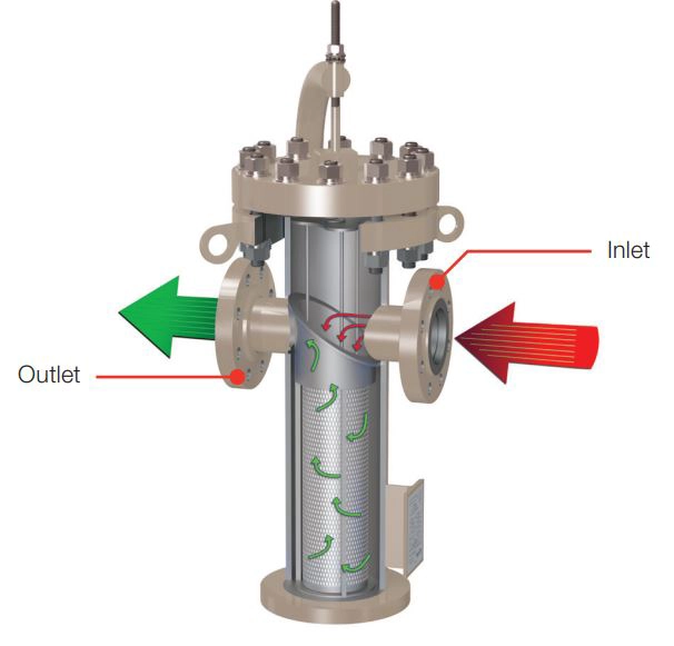
How it Works:
Natural gas enters the housing through a nozzle and passes through the filter cartridges. The flow direction is from outside to inside the filter elements, allowing for maximum utilization of the filter media. Several important design aspects include:
Units are manufactured to ASME code requirements and can be supplied with a variety of quick-opening closures and filter element styles to suit most applications.
The standard cartridge for dry gas filters is a high-efficiency pleated cartridge. This cartridge, with an inner core and an outer guard, should be designed to protect against erosion in high-flow applications and provide maximum dust-holding capacity (Figure 6).

For applications involving shear-sensitive solid contaminants, depth cartridges (Figure 7) are also available to capture particles deeper within the filter when they are crushed by impact with the media or support. The combination of three cylindrical fiber layers, together with an engineered gradient depth design in a single matrix, significantly enhances dust-holding capacity compared to conventional depth cartridges.
Advantages of this design over pleated cartridges include:

Another solution to reduce the weight of the filter and minimize the risk of damage, such as breakage, is the use of a guard made of sturdy polypropylene. Examples of this design are illustrated in Figures 8 and 8 for surface and depth filters, respectively.
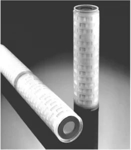

Another trick is the use of spiral roving on the outer surface of the media in pleated cartridges (Figure 10). These spirals prevent movement and deformation, protecting the media from damage.

The filter media must be such that it is not damaged or destroyed due to high-speed particle collisions that exist in many air and gas streams, and the presence of chemicals and water does not negatively affect its performance. Synthetic media are usually resistant to chemicals and water. By installing this type of media, the risk of failure due to corrosion or erosion of the cartridge is minimized.
Absolute grade polyester media provides the highest level of protection against tearing, swelling and chemical attack. Tearing and chemical attack can cause holes in the filter media. In this case, operators read a low pressure difference and mistakenly assume that the filter elements are clean and in good condition. Meanwhile, harmful contaminants seep through the holes in the media and contaminate downstream equipment. Swelling causes the pressure difference to increase rapidly, even when there may be a small amount of contaminant in the filter media. This reduces the life of the filter element and increases the need for its frequent replacement. Use polyester media to reduce these risks.
Glass fiber-based media face significant limitations in these applications due to their brittle nature. As can be seen in the scanning electron microscope (SEM) images of the media made of two different materials, in the exit path of the molecular deposition substrates in Figure 11, the polyester fibers (picture on the left) have a size and pattern due to their higher strength against gas flow. The pores are carefully controlled. In contrast, glass fibers, due to their brittle nature, exhibit irregular and unpredictable pore patterns, which can affect filtration performance.
But when the coalescing process is needed in addition to removing particles, a depth filter cartridge with a combination of polyester fibers and glass fibers is used.

Cellulose media impregnated with epoxy resin is also used in some applications where it is not possible to use polyester fibers due to chemical compatibility. Because cellulose is compatible with a wide range of chemicals and therefore can be used in connection with different types of gases such as nitrogen, ammonia and natural gas.
From the perspective of media production technology, spanband technique has been widely approved and accepted. Spunbond cartridges in gas applications offer significant performance advantages over resinbond and balloon melt cartridges because the media produced by this method have a controlled pore size and pattern (Figure 11). On the contrary, the Mellat balloon technique, as seen in the scanning electron microscope (SEM) image of Figure 12 (left), under the influence of the pressure caused by the passage of the gas flow, leads to the accumulation of fibers and the destruction of the media structure. On the other hand, in the band resin technique (Figure 11 on the right), the presence of resin causes the empty spaces between the fibers to be blocked, which leads to an increase in pressure drop. But on the other hand, the use of resin significantly reduces the migration of media fibers.

In the absorption dehydration process, water vapor is removed from the gas by intimate contact with a liquid desiccant. This contact typically occurs in packed or trayed towers. Glycols are commonly used as effective liquid desiccants. Adsorption drying with glycol is often more economically attractive than solid desiccant drying when both processes can achieve the required dew point.
Glycols used for natural gas dehydration include ethylene glycol (EG), diethylene glycol (DEG), triethylene glycol (TEG), and tetraethylene glycol (T4EG). Typically, a single glycol is used for dehydration, but sometimes a combination of glycols is economically viable. Triethylene glycol (TEG) is almost universally accepted as the most economically viable glycol due to its higher efficiency, lower operating costs, and reliable performance. TEG has been successfully used for the dehydration of both sweet and sour natural gases under a wide range of operating conditions. Dew point depressions of 40°F to 140°F can be achieved at gas pressures between 25 psig and 2500 psig and gas temperatures ranging from 40°F to 160°F. The extent of dew point depression depends on the equilibrium dew point temperature for a given TEG concentration and contact temperature. Increased glycol viscosity can cause issues at low contact temperatures, which may require heating the natural gas. Very hot gas streams are typically cooled before dehydration to prevent TEG evaporation.
Advantages of Glycol Dryer Systems:
The inlet gas must be cleaned to remove liquid water, hydrocarbons, wax, sand, drilling mud, and other impurities. These contaminants can cause severe foaming, overflow, increased glycol losses, reduced efficiency, and higher maintenance costs in the dehydration tower or adsorber. Scrubbers, separators, or filter separators can remove these impurities, especially in very dirty gases. Methanol injected at the wellhead as a hydrate inhibitor may cause several problems for glycol desiccant units. Methanol increases the heat requirement in the glycol recovery system, and liquid methanol pools can lead to overflow in the absorber. Additionally, methanol vapor exiting the recovery system along with the water vapor is hazardous and must be recovered or vented at non-hazardous concentrations.
Due to the highly corrosive and contaminated environment, glycol desiccant processes require an optimized filtration/separation system to function properly. Operational problems are rarely caused by a single contaminant. Solid and liquid contaminants in the adsorber inlet gas and circulating glycol stream can cause foaming, tray plugging, scale buildup in heat exchangers and reboilers, and pump seal failure.
Foaming in the absorber can result in glycol loss, reduced operating capacity, and substandard product production. A poorly designed filtration system can lead to frequent and unnecessary element changes, substandard gas quality, excessive downtime, and increased operating costs.
The flow chart in Figure 8 illustrates the process and flow of a typical glycol dryer. The drying process can be described as follows (this diagram serves as a general example of where filtration systems fit into the glycol drying process. These processes vary by company and facility, so each application must be individually evaluated to select the appropriate filtration system technology):
1. The inlet gas stream first enters the unit through an inlet gas filtration system to remove hydrocarbons, water, and other liquid particles. A particulate filter is often placed before the coalescer to remove solid particles and protect the coalescer. This filtration reduces foaming and fouling of the adsorbent and improves adsorption efficiency.
Poor removal of solids and liquids typically results in clogged contactor trays, reduced efficiency, and frequent foaming. These issues increase operating costs and reduce production. Inadequate removal of contaminants in the inlet gas can also lead to high contaminant levels entering the glycol regeneration loop, resulting in black or dark glycol—a key indicator of process performance. Symptoms include increased reboiler temperatures due to coking on the burners or poor heat exchanger efficiency due to fouling.
2. The wet gas is then introduced from the bottom of the gas-glycol contactor and allowed to flow upward through the trays, while the glycol flows downward through the column. The gas contacts the glycol in each tray, and the glycol absorbs water vapor from the gas.
3. The dry gas then passes through a vertical glycol/gas exchanger, usually constructed as a coaxial tube heat exchanger.
Here, the dry exhaust gas helps cool the hot regenerated glycol before it enters the contactor. The dry exhaust gas then leaves the unit from the top of the glycol cooler. A gas/liquid coalescer is usually located here to remove the glycol and any carried-over liquid contaminants, protecting downstream equipment and processes.
4. The rich glycol, which has absorbed water vapor from the gas stream, exits the contactor and is preheated by passing through a distillation system before being directed to the inlet of the flash separator. The flash separator allows the release of the associated dissolved gas at low pressure.
5. The separated gas in the flash separator is removed from the top of the separator tank and can be used as an auxiliary fuel for the reboiler. A gas/liquid coalescer is located here to remove the glycol, water, and carried-over hydrocarbons. The coalescer collects any liquid particles entrained in the gas and produces a clean gas that can be recompressed or used as fuel.
In the flash tank separator, any excess blowdown gas is vented through a back-pressure valve. The flash tank separator is equipped with a liquid level control and a motorized diaphragm valve that discharges the rich glycol stream through a heat exchanger coil into a storage tank to preheat it.
6. If the rich glycol stream in the contactor has absorbed liquid hydrocarbons, it may be desirable to use a three-phase flash separator or carbon bed to separate the glycol from the liquid hydrocarbons before the stream enters the reboiler. The presence of any liquid hydrocarbons in the reboiler can cause unnecessary loss of glycol. Therefore, the rich glycol stream leaving the flash tank enters a carbon bed to remove liquid hydrocarbons and chemical compounds. To protect the carbon bed, a particulate filter is placed upstream of the carbon bed to remove sediment and solid contaminants. Downstream of the bed, a particulate filter reduces foam and sediment by removing carbon particles and minimizing glycol loss.
7. The rich glycol is then heated in a heat exchanger and fed to the stripping column and reboiler. In the reboiler, the glycol is heated to evaporate the water from the glycol, producing lean glycol, and the separated water vapor is discharged from the column. The reboiler uses natural gas as fuel. The lean glycol is then stored in a tank that maintains a continuous supply for the glycol pump. The lean glycol is cooled using a heat exchanger and pumped back to the glycol contactor to continue the cycle.
8. Before entering the pump, the glycol passes through a high-pressure glycol filter to remove any foreign solids that may have been picked up and then enters the glycol pump.
9. The dry glycol from the glycol pump enters the top of the contactor and is injected into the upper tray. The glycol flows over each tray and is transferred to the next tray through a downpipe. The downpipe of the lower tray has a seal chamber that holds a liquid seal on the trays.

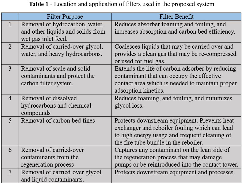
The information for this proposed filtration system is summarized in Table 1.
The benefits of an optimized filtration system in the glycol desiccant process include:
Removing water reduces the risk of hydrate formation and minimizes corrosion in process equipment and piping.
To maintain the efficiency of the absorbent beds, they must be protected from free water and liquid hydrocarbon contamination to achieve their expected lifespan.
The importance of filters in the glycol regeneration loop is very high. If inefficient filters are used in this loop, the system will be stressed by contaminants such as iron sulfide, silica, and liquid hydrocarbons that accumulate in the regeneration loop, leading to glycol degradation, foaming issues, and damage to pump seals.
Usually, to address the problems of the glycol dehydration unit, a multi-stage filtration system is used at the inlet of the contactor due to the high contamination load, and for the dry gas exiting the coalescer, a single-stage high-efficiency coalescer with an accuracy of 0.3 microns is used. Additionally, in the glycol regeneration loop, upstream of the carbon bed, liquid particle filters are used to protect and extend the life of the carbon bed. The liquid particle filter downstream of the carbon bed absorbs any remaining fine carbon particles.
[1] Guo, Boyan, and Ali Ghalambor. Natural gas engineering handbook. Elsevier, 2014.
[2] Sutherland, Kenneth S., and George Chase. Filters and filtration handbook. Elsevier, 2011.
Author: Amin Forouzan

 Save the post
Projects: