

The quality of the air inlet of the turbine is a critical factor influencing the performance and life of the gas turbine. Consequently, it is essential to implement a filtration system to manage air quality by eliminating pollutants present at the turbine inlet. Given the numerous factors involved, selecting an appropriate filtration system can be challenging. The system’s choice should align with the operational philosophy and goals of the turbine, account for the pollutants in the ambient air, and consider anticipated changes in pollutants due to temporary emission sources or seasonal variations.
A pollutant encompasses any substance trapped in the airflow entering the gas turbine. This may include solid particles, gasses, and liquids such as sea salts, dust, sand, exhaust gasses from factories, oil and fuel vapors, as well as particles like chemicals, fertilizers, minerals, and any industrial by-products. The types of pollutants in the turbine’s working environment heavily depend on its location, such as industrial sites, agriculture, etc. Pollutants can vary daily or seasonally due to exposure to changing weather conditions, including wind direction, wind speed, temperature, relative humidity, and precipitation. Each gas turbine site should undergo a comprehensive assessment for anticipated pollutants. The design of the inlet air filtration system must align with the expected pollutants in that specific environment.
Consequences of Inadequate Filtration
When the quality of the air entering the gas turbine is not effectively controlled, it can lead to various detrimental consequences. Among the most common degradation mechanisms in gas turbine systems are erosion, fouling, and corrosion.
Erosion: Erosion occurs when solid or liquid particles, typically around 10 micrometers in size or larger, impact the rotating or stationary surfaces within a gas turbine. These particles have a damaging effect on the surface, leading to the deterioration of fine metal components and ultimately causing a change in surface geometry. This alteration in geometry results in deviations in the airflow path, roughening of previously smooth surfaces, and a reduction in the cross-sectional area of metal components, particularly in high-stress areas. Erosion is an irreversible process, necessitating the replacement of gas turbine components to restore them to their original condition. Notably, particles larger than 10 micrometers can be effectively filtered out using appropriate filters.
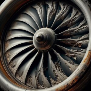
Fouling: As the particle size decreases, the degradation mechanism shifts from erosion to fouling. Particles that contribute to fouling are typically smaller than 2 to 10 µm. Fouling involves the accumulation of materials in cavities and low-flow areas within the airflow path. Small particles, along with substances like oil vapors, water, salts, and other sticky materials, either individually or in combination, create surfaces where they adhere. These particles adhere to the compressor and cooling paths, as well as turbine blades. This effect alters the surface clearances, increases surface roughness, disrupts rotational balance, obstructs flow paths, and diminishes the smoothness of rotating and fixed blade surfaces, ultimately resulting in a decrease in gas turbine performance.
Filters can effectively remove most particles causing fouling, although some sub-micron particles may be challenging to eliminate from the flow stream. Particles that accumulate and are not removed by the inlet filtration system may be addressed through compressor flushing. While this process can restore a significant portion of the compressor’s performance, it cannot fully restore the gas turbine to its original state.
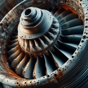
Corrosion: Corrosion is a common issue in gas turbines that can damage their surfaces. In the compressor section, wet deposits, salts, acids, and gases such as chlorine and sulfide can cause cold corrosion. On the other hand, the combustion and turbine sections can experience high-temperature corrosion, also known as “hot corrosion”. This type of corrosion occurs when the metal surface interacts with other chemical substances at elevated temperatures, resulting in accelerated oxidation. The process involves a chemical reaction between a component and molten salts that are deposited on its surface. Predicting the rate of hot corrosion can be challenging due to its complex nature.
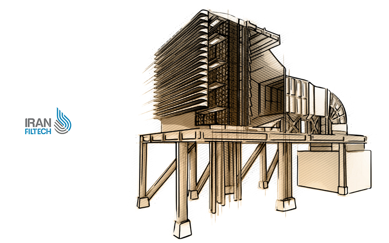
Turbine Air Filtration System
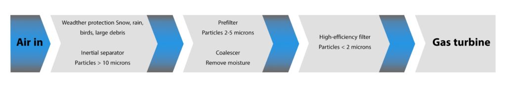
Gas turbines require various types of filters for purification. The commonly used method for cleaning turbine inlet air involves multi-stage filtration systems, which typically consist of two or three stages. Each stage serves a specific purpose and is designed accordingly. However, it’s important to note that this filtration approach may not be universally applicable, as the effectiveness of the filtration process is significantly influenced by the specific operating environment. Factors like the surrounding vegetation, weather events, and other considerations come into play and can impact the effectiveness of the filtration steps.
In the process of designing filtration systems, it is common to use a pre-filter as the first stage to remove erosive particles, rain, and snow. The second filter can either be a low- or medium-efficiency filter, which is suitable for capturing finer particle types, or a coalescer that is selected to eliminate liquid droplets. The third filter is typically a high-efficiency filter, which is specifically designed to remove smaller particles, especially those that are less than 2 microns in size, from the incoming air stream.
Filters Used in Gas Turbines
To meet the diverse requirements of various filter parameters and operating environments, a range of filters has been developed, each offering unique capabilities. These filters span from high-efficiency self-cleaning filters to those designed specifically for the removal of liquid droplets from the airflow. Below are descriptions of some specifications for these filter types.
Protectors Against Weather Conditions
Air louvers, hoods, and screens are essential filtration mechanisms that help to reduce moisture and coarse particles from entering into the primary filtration system. Although these devices are not precisely known as filters, they play a vital role in removing large objects or particles carried in the inlet stream.
Hoods and air louvers are widely used in most inlet filtration systems, particularly in regions with high rainfall or snowfall. In tropical climates, hoods redirect significant amounts of rainwater, preventing inertial separators from overloading and minimizing the water reaching downstream high-efficiency filters. Medium-sized hoods are highly efficient in deflecting rain, and the recommended maximum inlet velocity for rain deflection is 650 feet per minute. In polar environments, hoods help minimize snow penetration. Overall, it is highly advisable to use hoods or other weather protection systems in systems that are equipped with high-efficiency filters.
Inertia separator
This equipment utilizes physical principles such as momentum, gravity, centrifugal forces, collisions, and physical differences between phases to remove or discharge particles from the gas stream. As dust or water particles move within the airflow, they are pushed forward while the air is deflected towards the ports and exits in a different direction. The most common types of inertial separators used for gas turbine inlet filtration are vane and cyclone separators, with a maximum inlet velocity of 650 feet per minute for rain deflection. In polar environments, hoods can be used for added protection.
Prefilters
Air is a mixture of particles, some of which are large and others are small. If we use high-efficiency single-stage filters, the accumulation of these particles can cause the filter to become overloaded and lead to increased pressure drop. To prevent this, we use pre-filters that absorb larger solid particles and increase the lifespan of high-efficiency filters. Pre-filters can capture solid particles larger than 10 microns, and some can even capture particles in the 2-5 micron range. Typically, pre-filters are made of large-diameter synthetic fibers and come in a disposable frame construction. Bag filters are also commonly used as pre-filters.
Moisture Coalescers
In environments where the air contains high moisture content, coalescers are necessary to remove liquid moisture. These filters work by capturing small water droplets in their fibers. The filtration process causes the liquid droplets in the gas to combine and form larger particles, which can then be separated by gravity. Coalescers are designed to allow these larger droplets to either exit the filter or re-enter the air stream where they can be captured by a downstream separator. The figure below illustrates the mechanism of the coalescing process.
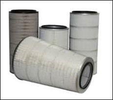
High-efficiency filters
High-efficiency filters are designed to filter smaller particles effectively. The filter media in these types of filters is made up of materials such as fiberglass, processed paper, or synthetic fibers. These materials consist of many randomly oriented micro-fibers. High-efficiency filters use various filtration mechanisms to achieve optimal performance in removing polluting particles. There are different types of high-efficiency filters, including rectangular, cylindrical/cartridge, and bag filters. The three most common types of high-efficiency filters are EPA, HEPA, and ULPA. EPA and HEPA filters have a minimum efficiency of 85% and 99.95%, respectively, for all particles greater than or equal to 0.3 microns. ULPA filters have a minimum efficiency of 99.9995% for particles of 0.12 microns or larger.
High-efficiency filters are used in gas turbines to remove impurities from the air. These filters have a pleated media which increases the filtration area. To achieve high filtration efficiency, the flow through the filter media fibers is restricted, which causes a high-pressure drop. However, the folds in the filter help reduce this pressure drop. The initial pressure drop in high efficiency filters can be up to 1 inch of water, with a final pressure drop ranging from 2.5 inches of water for rectangular filters to 4 inches of water for cartridge filters. It’s important to note that the life of these filters is strongly influenced by other forms of filtration upstream of high efficiency filters. If there are filtration steps to remove larger solids and liquid moisture, these filters will last longer. High efficiencyfilters are rated under different standards.
Most filters used in gas turbines are not classified as EPA, HEPA, or ULPA. Most of these filters are rated under ASHRAE 52.2:2007 and EN 779:2002 standards.
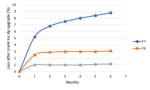
The importance of choosing a filter with high efficiency
According to studies, the impact on gas turbine power reduction is less significant when using a high-efficiency filter with greater pressure drop than when the intake air quality is poor. AAF International has collected data that illustrates this phenomenon. The chart below provides an example where the gas turbine with an F7 filter (lower filtration efficiency) experienced a notable reduction in performance compared to the gas turbine with F9 and H12 filters (higher filtration efficiency) due to sedimentation.
Media used in gas turbine filtration
When it comes to filtering gas turbines, the selection of filter media depends on various factors such as the location, environment, desired filtration efficiency, pressure drop, and mechanical properties. There are different types of filter media available such as cellulose, a mixture of cellulose and polyester, glass microfibers, a mixture of glass microfibers and synthetic fibers, and composite structures containing a layer of meltblown or electrospun. Glass or synthetic fiber mats can also be used as pre-filters. They wrap around the final filters to provide an extra layer of filtration.
Nanofiber for gas turbines
In recent years, there has been a growing interest in the research and development of nanofibers due to their ability to enhance the performance of various filter media. Nanofibers are extremely tiny fibers in the nanometer range that can help improve filtration efficiency and reduce pressure drop in filtration systems. However, the mass production of nanofibers at a reasonable cost remains a challenge. As a result, current nanofiber filtration media is typically used in conjunction with other conventional media.
One of the most prominent methods of nanofiber production is the electrospinning method. This process involves the use of a needle, nozzle, or moving emitter. These tools produce polymer liquid solutions, which are then attracted to the collection area by a high-voltage electrostatic field.
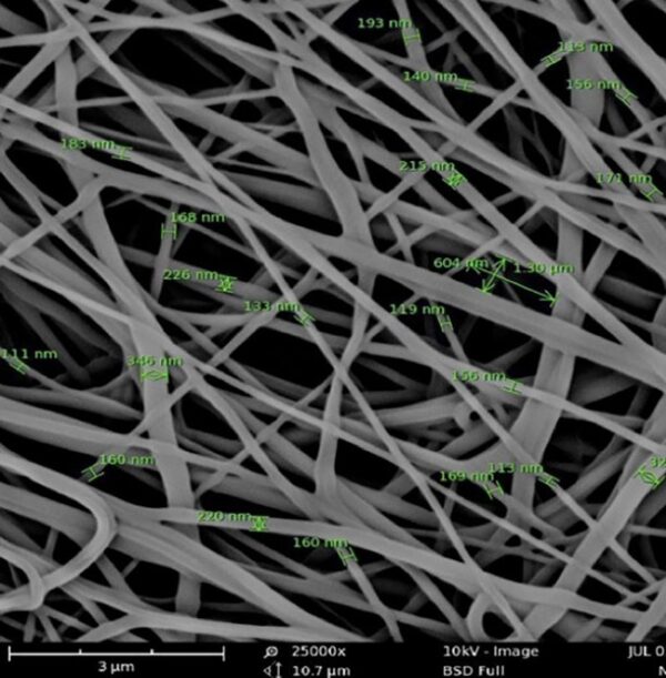
As the polymer and dissolved solvents are drawn out of the emitter and accelerated through the electrostatic region, fibers are formed through the process of solvent evaporation One of the most popular techniques for producing nanofibers is the electrospinning method. This process involves the use of a needle, nozzle, or moving emitter to produce liquid polymer solutions. These solutions are then attracted to a collection area by a high voltage electrostatic field. As the polymer and dissolved solvents are drawn out of the emitter and accelerated through the electrostatic field, fibers are formed through the process of solvent evaporation.
Currently, electrospun nanofiber meshes find significant applications in air filtration markets such as engine air intake filters, turbine air filters, pulse filters for dust collection systems, and vacuum bag filters.
Nano filters in gas turbines
It has been proven that sub-micron air pollution, such as aerosol, can deposit in the compressor of a gas turbine, leading to a decrease in output power. To improve the efficiency of gas turbine inlet filters, electrospun nanofibers with a diameter of 0.25 microns have been used in a conventional filter bed. The benefits of using nanofibers in gas turbine inlet air filters and other industrial filtration applications have been proven for over twenty years. Recent advances in electrospun nanofiber technology have increased the filter efficiency of gas turbine inlet filters by providing minimal pressure drop. In addition, it has improved the durability of nanofibers in high-temperature and humidity applications.
Prominent global companies in the field of using nanofilters in gas turbines
Currently, prominent companies in the field of filtration are using this technology to improve the media of the gas turbine filtration system. One common example of such media is a combination of cellulose and synthetic fibers coated with electrospun nanofibers, which has been used in companies such as American Air Filter Company (AAF) and HENGST FILTRATION (Nordic air).
New technology in the production of nanofibers
H&V Company is a reputable filter media manufacturer that has recently introduced a new technology for nanofiber production. Although electrospinning is an effective method for creating nanofibers, it has several drawbacks. Firstly, the electrospinning process is quite slow, which increases production costs when producing nanofibers on a commercial scale. Secondly, electrospinning only produces a two-dimensional structure, which is not ideal for deep-loading applications. Although this configuration is suitable for surface loading, it has limited capability for deep-loading applications. Thirdly, electrospun nanofibers are relatively weak and can easily detach from the substrate or get damaged. As a result, there is a need for reinforced nanofibers that can overcome these shortcomings of electrospun nanofibers.
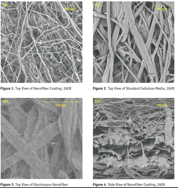
A novel solvent-free nanofiber coating technology has been developed that offers improved flexibility, control, and durability compared to the traditional electrospinning process.
This new nanofiber coating is composed of fibers with a diameter ranging from 0.3 to 0.5 microns, which can be extended up to 1 micron. The fiber diameter distribution and layer thickness can be easily adjusted based on the specific application. By utilizing this nanofiber technology, a wide range of filtration media can be enhanced.
A new nanofiber layer, with a thickness ranging from 15 to 30 microns, can be applied directly to the macrofiltration substrate. When used as a standalone substrate, the thickness of these nanofibers ranges between 100 and 200 microns. Nanofiber coatings can be applied to any nonwoven material like glass, cellulose, or synthetic fibers. However, electrospun coatings require critical resins for adhesion.
Nanofibers can be arranged in multiple layers and placed in different areas of the filter media according to their intended use. For instance, in a gas turbine or heavy air application, the nanofiber layer can be placed upstream, before the microfiltration bed, to enhance surface filtration performance. Similarly, if the aim is to improve depth filtration, the nanofiber layer can be placed downstream of the microfiltration bed.
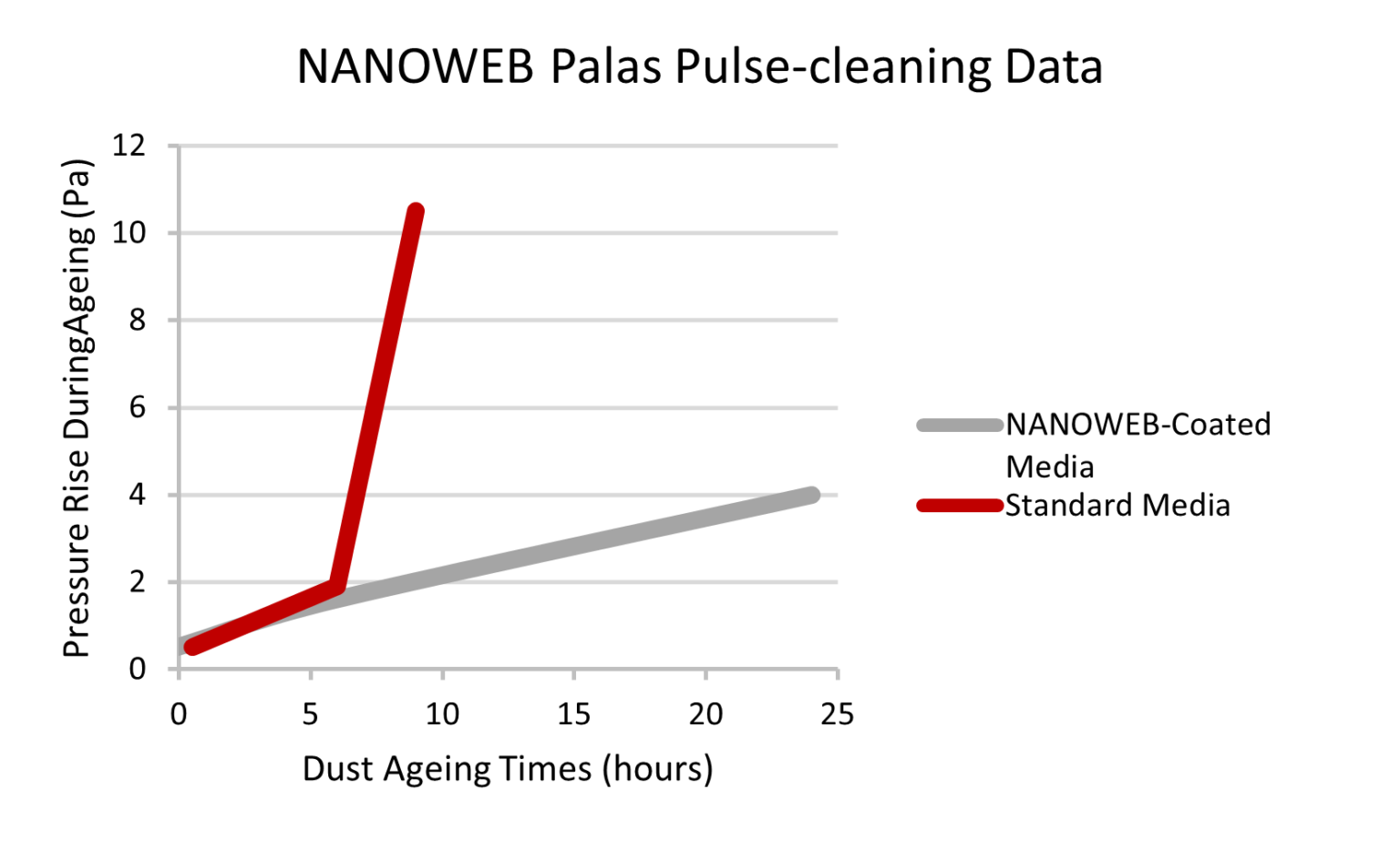
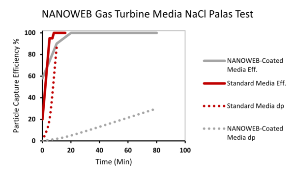
In graphs 10 and 11, there is a comparison of the pressure and efficiency of two samples of standard media and coated with nano fibers produced by h&v company.
Conclusion
The effects of air intake filtration have both positive and negative aspects. On the one hand, any obstruction in the air entering the gas turbine results in a pressure drop, which is a downside of filtration. On the other hand, a suitable filtration system helps maintain the performance of gas turbines and minimizes the possibility of destructive effects on equipment such as compressors and turbine blades. Although unfiltered or less filtered air provides better performance initially due to the lower pressure drop, polluted air can gradually lead to temporary or permanent damage to parts and equipment. Therefore, the key challenge is to minimize the pressure drop while increasing the particle and moisture removal efficiency. One solution to this challenge for effective filtration is the use of multiple stages of filtration to remove different substances from the air. In the initial stages of gas turbine filtration, larger particles such as rain and snowdrops, dust, smoke, or dust and particles must be removed. Then, filters with higher efficiency should be used to remove smaller particles. It is also important to pay attention to the correct selection of filters, repair, maintenance, and timely and appropriate replacement of the filtration system to increase the performance and life of the gas turbine.
Author: Forough Khalili
September 2023

 Save the post
 Projects: