


Desalination is commonly used today to address freshwater shortages in certain regions of the world where saline water is available. Over the past century, various technologies have been introduced. This article examines current commercial technologies such as Multi-Stage Flash Distillation (MSF), Multi-Effect Distillation (MED), and Reverse Osmosis (RO), as well as emerging technologies aimed at utilizing renewable energy sources such as wind, solar, and biomass energy. In these cases, desalination equipment remains similar to conventional systems, with the primary difference being the use of renewable energy. Therefore, classifications are first introduced based on operating principles, the main energy input required for treatment, and the potential for integrating renewable energy sources. The operational mechanisms of these processes and some data regarding their development status are also reported.
To meet the growing demand for freshwater due to population growth and increased living standards, the first desalination systems were installed in the late 1950s. The initial technologies relied on thermal energy due to the low cost of fossil fuels. However, as energy costs gradually increased, extensive research was conducted to minimize the overall cost of water desalination. These studies have been carried out with two main objectives: (1) improving the energy efficiency of conventional commercial technologies and (2) exploring and developing innovative solutions.
For example, in the first approach, the number of stages in Multi-Stage Flash Distillation (MSF) has gradually increased from 8–12 stages to 20 stages, enhancing efficiency. Regarding innovative solutions, the introduction of semipermeable membranes marked a fundamental shift in desalination technology. Today, Reverse Osmosis (RO) has become the most widely used desalination technology.
The term desalination refers to the technological process used to extract freshwater from saline water. Seawater is often the primary raw water source used for this process. Historically, the concept of desalination was introduced by the Royal Navy (the British naval force) at the end of the 18th century to enhance naval autonomy without the need for carrying additional water supplies on ships. Since steam engines powered ships during that era, the first desalination technology was single-stage flash distillation, which was later improved into the more efficient Multi-Stage Flash Distillation (MSF) in subsequent years.
The first type of desalination unit was built in Glasgow, Scotland, in 1885. Until World War II, the construction of desalination units remained exclusive to the company that later became known as Weir Westgarth. In the following years, desalination plants were installed worldwide for civil purposes. In 1907, a Dutch company installed the first desalination plant in the Gulf region, specifically in Jeddah. That plant was later replaced in 1928, with two new units supplied by Weir Westgarth, featuring a total capacity of 135 cubic meters per day.
Today, desalination can be carried out using various technologies. In general, a desalination plant consists of multiple processes to obtain fresh water, with the desalination unit being the most energy-intensive component. A typical desalination plant includes the following stages:
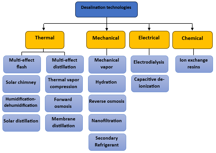
As previously mentioned, the desalination process accounts for the highest energy consumption within the treatment system. Therefore, this article will focus primarily on this stage. Before introducing the available solutions, a classification is necessary. Alkaisi [5] proposed three main categories:
Figure 1 illustrates an improved classification based on Alkaisi’s model, incorporating new technologies currently under investigation.

Evaporation and condensation technologies were the first desalination techniques historically used for producing freshwater in urban areas. In these technologies, seawater is converted into vapor through the application of thermal energy, followed by condensation. This energy can be supplied either through heat generated from a thermal process (e.g., combustion of fuels) or through mechanical processes.
In the first case, the most common technologies include:
Currently, other emerging methods are under investigation, some of which incorporate solar energy solutions, such as:
In mechanical processes, the primary technique used for producing freshwater through evaporation and condensation is Mechanical Vapor Compression (MVC).
Filtration-based solutions primarily rely on semipermeable membranes, which exhibit selective behavior based on molecular size and composition. The only exception is ion exchange resin (IXR), where natural or synthetic materials are used to chemically absorb dissolved ions.
Among these technologies, Reverse Osmosis (RO) is currently the most widely used desalination method. Electrodialysis (ED) and Ion-Exchange Resins (IXR) are employed to produce water with extremely low salt concentrations. Other emerging techniques, such as Forward Osmosis (FO), Nanofiltration (NF), and Capacitive Deionization (CDI), are still under development.
Crystallization-based technologies include techniques that extract freshwater in the form of ice crystals as an intermediate product. The main technologies in this group are:
It is important to note that all these approaches remain under investigation and are still in the research and development phase. Figure 2 illustrates the evolution of desalination processes over time.

Another useful classification can be established by considering the type of energy required to operate the desalination process, as illustrated in Figure 3. This classification is particularly relevant for selecting renewable energy sources to power desalination technologies. In this framework, four types of energy are considered:
Thermal Energy-Based Technologies
In this category, energy is supplied through fuel combustion, solar heat, or geothermal sources. Technologies that rely on thermal energy include:
It is noteworthy that the last three technologies (SC, HDH, and SSD) are specifically designed to directly utilize solar energy.
Mechanical Energy-Based Technologies
This group includes desalination technologies that require mechanical energy as their primary input:
All of these technologies rely on pumps and compressors, which account for a significant portion of the total energy consumption in these systems.
Electrical and Chemical Energy-Based Technologies
The last two categories have more limited applications:
Energy Conversion Considerations
It is important to note that mechanical and electrical energy can be easily converted with high efficiency. For instance:
This classification provides valuable insights into selecting appropriate renewable energy sources for sustainable desalination applications.
Thermal energy is a distinct case since it can be easily generated using electricity through the Joule effect or heat pumps. However, converting thermal energy into mechanical or electrical energy requires heat engines, which generally have lower efficiency compared to direct mechanical or electrical energy utilization due to thermodynamic and technical limitations.
It is important to note that thermal energy sources can, under specific conditions, be adapted for electricity generation. For example, if a high-temperature geothermal source is available, it is possible to construct a power plant to generate electricity.
Renewable Energy Sources for Desalination
To effectively power desalination processes with renewable energy, it is essential to identify energy sources that can generate electricity (or mechanical energy) from thermal energy sources. For this purpose, renewable energy sources can be classified based on their energy output efficiency, as follows:
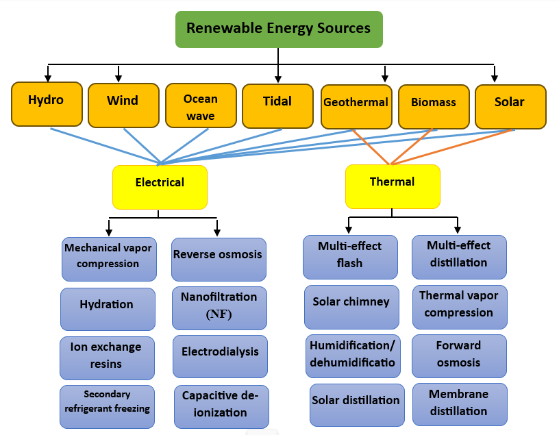
The efficiency of energy conversion depends on the characteristics of the local energy source. By integrating renewable energy technologies with desalination methods, the classification presented in Figure 4 is obtained. The following sections will introduce each of these methods in detail.
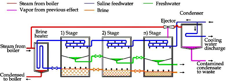
A Multi-Stage Flash Distillation (MSF) system typically consists of a series of twenty or more chambers, each operating at a progressively lower pressure than the previous one. As heated saline water flows from one chamber to the next, a portion of it rapidly evaporates (flashes) due to the pressure drop. The resulting water vapor passes through moisture separators, which remove any entrained brine droplets trapped in the vapor. The purified vapor then condenses on the cooler condenser tubes, forming distilled water that drips into collection trays. From these trays, the desalinated water is directed to a storage tank for further use.
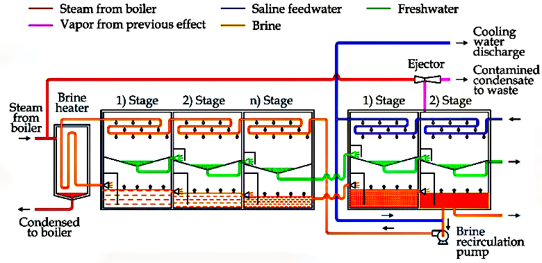
In recent years, a minor modification has been introduced to the MSF process. Instead of a condenser, a heat rejection section consisting of two or three flash stages has been added (Figure 6). More specifically, in this section, seawater is used as a cooling fluid. After this stage, part of the seawater is discharged, while the remaining portion is mixed with a fraction of the brine extracted from the last flash stage. This saltwater solution is then recirculated into the main desalination unit. This technique is employed to enhance the energy efficiency of large-scale desalination plants, typically consisting of 19 to 40 flash stages and 2 to 3 heating units.
A Thermal Vapor Compression (TVC) distillation system typically consists of two to six evaporator stages and operates using a multi-stage thermal compression process at very low temperatures and sub-atmospheric pressures.
In a standard four-stage unit, as illustrated in Figure 7, the process operates as follows:
In the fourth stage, some of the generated steam at 46°C and 0.1 bar is drawn by a thermal compressor, which compresses it together with high-pressure steam at 0.22 bar and recirculates it into the first stage as heating steam.
The condensed steam from each evaporation stage, along with the condensate from the condenser stage, is collected by a pump to form the final distilled water product.
Thermal vapor compression (TVC) distillation plants can produce high-purity water from any saline water source, such as seawater, without requiring complex pre-treatment or filtration systems.
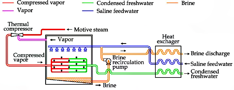
Vapor Compression (VC) is a widely used technique in distillation-based desalination, relying on the liquid-vapor phase transition. To explain the process, Figure 8 illustrates a Mechanical Vapor Compression (MVC) unit.
In this system:
To minimize energy consumption, a heat recovery exchanger is used to transfer heat from the discharged brine. After preheating, the incoming seawater is mixed with the brine stream. This saline solution is then sprayed externally onto the main heat exchanger inside the desalination unit.
Energy Considerations and Application
MVC desalination systems primarily require electricity for operation. Due to their efficiency and flexibility, small-scale, standalone desalination units using MVC technology can be designed to meet freshwater demands ranging from 100 to 3,000 cubic meters per day.

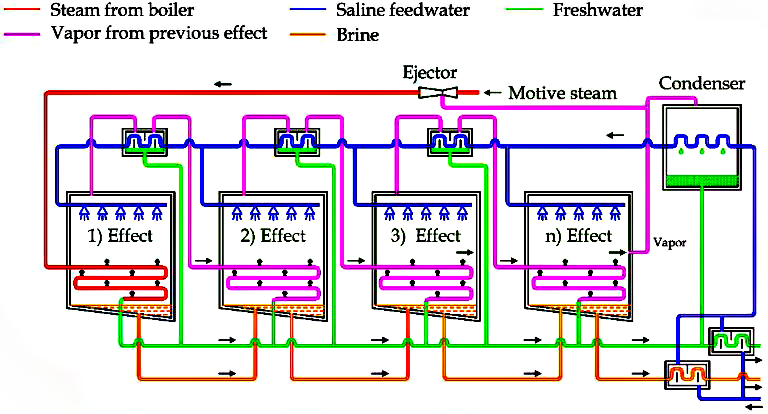
The same approach is adopted in the Thermal Vapor Compression (TVC) unit, as illustrated in Figure 9. The only notable difference lies in the method used to increase the vapor pressure. In a TVC system, a thermal compressor is utilized instead of a mechanical compressor. This thermal compressor operates using high-pressure steam, which is typically supplied from a power plant or another external thermal energy source.
TVC requires both thermal and electrical energy—the former for thermal compression and the latter for circulation pumps.
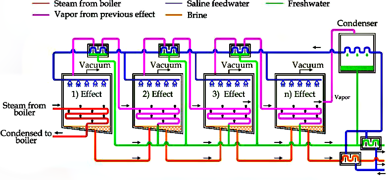
In some cases, TVC is integrated with Multi-Effect Distillation (MED) units, forming a hybrid desalination system known as MED-TVC, as illustrated in Figure 10.
This combined system has several differences compared to a standard MED system:
This configuration is typically employed to meet large-scale freshwater demands, ranging from 10,000 to 30,000 cubic meters per day.
For many years, seawater desalination was only carried out in relatively small quantities, such as on passenger ships or in desert towns, due to the high energy consumption of distillation processes. However, the development of Reverse Osmosis (RO) desalination in the early 1960s, using membranes as a separation medium, completely revolutionized the desalination industry. It made desalination significantly more accessible, though it still remains more expensive than deep-bed filtration.
The first membrane-based process designed primarily for seawater desalination used a high-pressure membrane to allow water molecules to pass through while blocking dissolved substances in the feed solution. The membrane is impermeable to ions and most dissolved molecular species.
Principle of Osmosis
To better understand osmosis, imagine a container divided into two sections by a vertical barrier, which is permeable only to water molecules. One side is filled with pure water, and the other side is filled with an equal level of saline water.
In this initial state (Figure 11-a), water will naturally flow from the pure water side to the saline solution in an attempt to equalize the salt concentration across both compartments. However, complete equilibrium cannot be achieved since an infinite amount of pure water would be required.
As osmosis continues, the volume of the saline solution increases while the pure water level decreases, creating a difference in liquid heights between the two sides. This leads to a hydrostatic pressure difference across the barrier, which slows down the movement of water toward the saline solution.
Eventually, a physical equilibrium is reached (Figure 11-c), where the hydrostatic pressure counteracts the osmotic force, and the water flow stops. The pressure at which this occurs is known as the osmotic pressure (ΔPosm).
The osmotic pressure varies based on the salt concentration and temperature of the solution—higher concentrations and temperatures lead to higher osmotic pressure.
Principle of Reverse Osmosis
If the saline solution compartment is enclosed and externally pressurized, water is forced in the opposite direction, passing through the semi-permeable membrane, and exiting the solution (Figure 11-d). As the applied pressure exceeds the osmotic pressure, the flow is reversed, which is the fundamental concept of Reverse Osmosis (RO).
It is important to note that no membrane can achieve 100% salt rejection, meaning that the permeate water obtained from RO will always contain a small amount of salt. The exact purity of the water depends on both the salinity of the feedwater and the salt permeability coefficient of the membrane.
Operating Pressures in RO Systems
Reverse Osmosis is a high-pressure process:
The osmotic pressure of seawater typically ranges between 34 to 42 bar.
The net operational pressure required for economic freshwater production is between 17 and 28 bar.
As a result, the actual applied operating pressures in RO systems are typically 50 to 70 bar for seawater.
For brackish water, applied pressures vary between 14 to 48 bar, depending on the salinity level of the feedwater.
The rate of pure water permeation through the membrane is proportional to the difference between the applied pressure and the osmotic pressure—essentially, the net driving force.
As this pressure difference increases, the water flow rate through the membrane also increases, while the salt flow remains constant.
This means that an increase in pressure and flow rate results in lower salt concentrations in the product water (permeate), improving desalination efficiency.

The most critical factor in the RO desalination process is the proper selection of the membrane, which is responsible for separating salt from water. Early RO membranes were made from cellulose derivatives, but today, a large percentage are manufactured from synthetic polymers.
There are two primary membrane configurations commonly used in reverse osmosis:
Hollow Fiber Membranes
A hollow fiber module consists of a bundle of hollow fibers, each with a salt-rejecting layer on the outer surface.
Filtration Process in Hollow Fiber Modules:
Hollow fiber modules offer a compact design, and the high membrane surface area, resulting from the dense fiber packing, compensates for the relatively lower water permeability of this configuration.
Spiral-Wound Membranes
A spiral-wound element typically consists of a flat-sheet membrane placed on a porous polyester backing sheet.
Filtration Mechanism in Spiral-Wound Modules:
Each membrane configuration has its unique advantages, and the selection depends on operational requirements, feedwater characteristics, and system design constraints.

Challenges in Reverse Osmosis (RO) Systems
The narrow flow channels in reverse osmosis (RO) modules can be easily clogged by fine particles. Therefore, pre-filtration systems must be installed to remove such particles before they reach the RO membranes, ensuring optimal performance and longevity of the system.
As introduced in the previous section, Forward Osmosis (FO) refers to the natural osmotic process, in which the solvent (water) moves from a dilute solution to a more concentrated solution, provided that the two solutions are separated by a semi-permeable membrane.
Interestingly, two solutions with different solutes but equal osmotic concentration and temperature will exhibit the same osmotic pressure.
This means that it is possible to extract freshwater using a solution with a higher concentration than seawater.
Example: Hydration Bags for Emergency Use
This principle is applied in “hydration bags,” which serve as emergency water purification kits. These bags contain a semi-permeable membrane and are filled with sugar-based solutions.
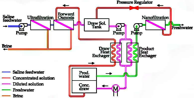
Trevi Systems’ Forward Osmosis Model
A forward osmosis desalination system, proposed by Trevi Systems, is illustrated in Figure 13.
Process Overview:
Development Status
This technology is still in the development phase, but it offers promising potential as an energy-efficient desalination method compared to traditional RO systems.
Nanofiltration (NF) is a membrane filtration process used to remove dissolved ions or organic compounds to produce soft water, meaning water with a limited number of ions (e.g., Ca²⁺, Mg²⁺).
This technique is conceptually similar to Reverse Osmosis (RO). The main practical difference lies in how ions are removed from saline water, as illustrated in Figure 14.

NF Nanofiltration is used in various applications, including water and wastewater treatment, pharmaceuticals, and food processing. However, its use for seawater desalination is limited, as nanofiltration membranes are more porous and allow some dissolved solids to pass through.
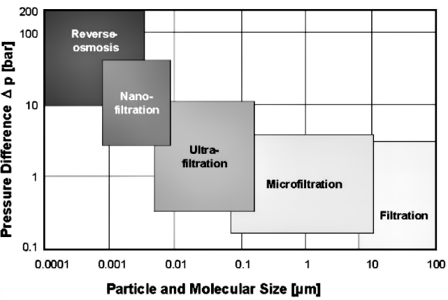
As illustrated in Figure 15, filtration technologies are classified based on the size of particles and molecules that the membrane can retain.
The prefix “Nano-” refers to the pore size, which ranges between 1 to 10 nanometers in nanofiltration membranes. This makes NF more selective than microfiltration and ultrafiltration but less restrictive than RO.
Separation Efficiency
Since NF-treated water contains more residual ions than RO-treated water, a lower pressure gradient is required across the membrane (34 to 48 bar).
Energy Considerations
Because NF requires less energy compared to RO, this technology is currently being evaluated for seawater desalination applications as a potentially more energy-efficient alternative.
Desalination using the Reverse Electrodialysis (RED) process is less commonly used compared to Reverse Osmosis (RO). This method employs two types of ion-exchange membranes:
Electrodialysis was originally a laboratory-scale process, primarily used to remove salts from specific colloidal solutions. However, the development of ion-selective membranes—capable of differentiating between anions and cations—has revitalized this process, making it a potential candidate for desalination applications.
How Reverse Electrodialysis Works
As illustrated in Figure 16, ions from the feedwater (which is to be desalinated) move toward the membranes under the influence of an applied electric field:
Each ion stream is then stopped by the next membrane, as each subsequent layer is permeable only to ions of the opposite charge. As a result, the ions are retained in alternating compartments, where they combine to form a concentrated brine solution.
This method offers a different approach to desalination and is being explored as a potentially energy-efficient alternative for specific applications.

In practice, an electrodialysis system typically consists of a large number of such compartments, which are alternately separated by anion-exchange and cation-exchange membranes.
The electrolyte solution, which comes into contact with the electrodes—where electrochemical reactions take place—is circulated in a separate circuit.
At regular intervals, the electrode polarity is reversed, causing the ions to move in the opposite direction, effectively switching the positions of the brine and product water compartments.
This automatic polarity reversal acts as a self-cleaning mechanism for the membranes, eliminating the need for chemical cleaning agents and enhancing operational efficiency.
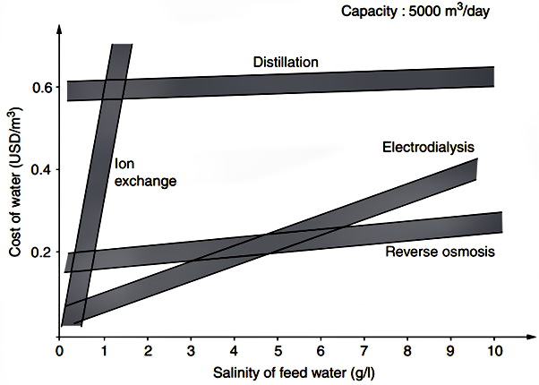
Some insights into the typical operational costs of desalination processes are presented in Figure 17, plotted against feedwater salt concentration.
Although the cost data may be somewhat outdated, the relative cost differences between various desalination processes remain largely accurate.
It can be observed that, for all but the lowest salt concentrations, Reverse Osmosis (RO) remains the most cost-effective option.
It is evident that membranes play a crucial role in providing high-purity water. Processes such as salt removal (Reverse Osmosis and, more recently, Nanofiltration), high-quality filtration, trihalomethane reduction, and silica removal are all made possible by the use of appropriate membrane-based technologies.
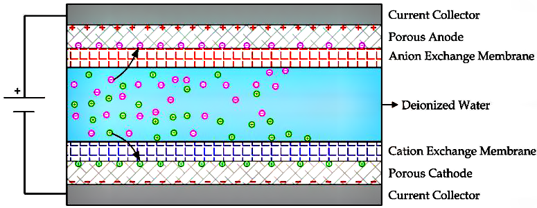
Similar to Reverse Electrodialysis (RED), Capacitive Deionization (CDI) utilizes an electric field applied between two carbon electrodes connected to a direct current (DC) voltage source.
However, a phenomenon known as co-ion adsorption—where ions with the same charge as the electrode surface are also attracted—limits the efficiency of this technology.
As illustrated in Figure 18, energy efficiency can be enhanced by integrating anion-exchange and cation-exchange membranes onto the electrodes. This modified approach is known as Membrane Capacitive Deionization (MCDI).
Advantages and Development Status
Despite these advantages, CDI remains an emerging technology and is still in its early research and development stages.
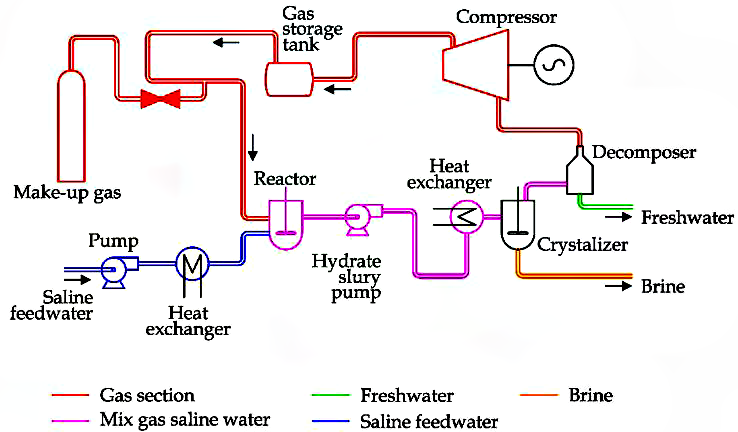
Hydration (HY) desalination is based on the formation of gas hydrates, which are crystalline solids composed of water molecules (host) and gas molecules (guest) such as nitrogen, carbon dioxide, and methane.
A schematic of a hydration desalination unit is illustrated in Figure 19.
Process Description
Development Status and Challenges
Secondary Refrigerant Freezing (SRF) is a desalination process based on the liquid-to-solid phase transition. Since the formed ice contains only a limited amount of salt, this method can be used to produce freshwater from seawater.
A refrigerant is used to freeze the saline water. However, the main challenge in this process is removing the produced ice efficiently.
One proposed solution involves utilizing the low temperatures available during the regasification of liquefied natural gas (LNG) to freeze seawater and obtain ice.
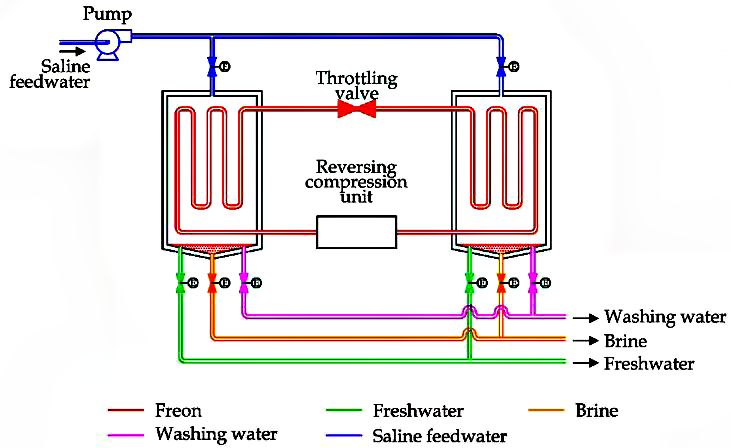
Another solution is illustrated in Figure 20, featuring a system composed of two chambers, a reverse-cycle heat pump, and solenoid valves.
Process Description
This unit alternates between producing ice and freshwater in either the left or right chamber:
Development Status
This desalination technique is still under development. While it presents an alternative approach, challenges related to system efficiency, scalability, and cost-effectiveness remain areas of ongoing research.
Membrane Distillation (MD) is a desalination process based on hydrophobic membranes, which allow water vapor molecules to pass through while blocking liquid water.
In theory, MD can completely reject all non-volatile solutes, including dissolved salts. However, the main drawback of the MD process is its high energy consumption, primarily due to the liquid-to-vapor phase change and incomplete latent heat recovery.
For these reasons, MD is not energy-efficient when used as an independent system. However, it offers some operational advantages:
MD Configurations
MD systems can be assembled in four different configurations, as illustrated in Figure 21.
The simplest method is Direct Contact Membrane Distillation (DCMD), where:
Applications
This technology is commonly used in:
Despite its high energy demand, MD remains an area of active research, particularly for low-energy desalination applications.

The term “Ion-Exchange Resin (IXR)” refers to various organic compounds specifically designed for chemical reactions with dissolved ions. These resins capture specific ions from the solution and release other ions from the resin into the solution.
Historically, zeolites, a class of minerals with ion-exchange properties, were used for this purpose. Today, ion-exchange resins are widely applied in both industrial and domestic applications, such as:
Classification of IXR Based on Functional Groups
IXRs can be classified based on their functional groups:
Cation-Exchange vs. Anion-Exchange Resins
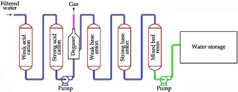
This technology was developed in the late 1960s. A schematic of an IXR-based water desalination unit is shown in Figure 22.
IXR Desalination Process
Regeneration of Ion-Exchange Resins
During the ion-exchange process, the resins gradually become saturated with captured ions. Therefore, periodic regeneration is required:
This cyclical regeneration allows the continuous reuse of resins, making IXR an efficient and scalable desalination technology.
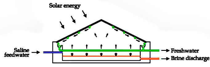
Solar Still Distillation (SSD) can be performed using a blackened basin containing saline water and air, enclosed by a tilted glass cover.
The working principle is as follows:
A possible system design is illustrated in Figure 23.
System Characteristics
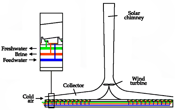
A solar chimney desalination unit can be assembled as shown in Figure 24.
A large solar collector shaped like a chimney, made of transparent materials (glass or plastic), is used to convert solar radiation into kinetic energy for air movement.
If a small wind turbine is installed, the airflow inside the system can be used to generate electricity.
The solar collector consists of several small SSD units, utilizing solar energy to produce freshwater.
This technology is still under investigation.
The Humidification-Dehumidification (HDH) system is a new thermal desalination method based on carrier gas.
In detail, freshwater can be obtained by condensing air moisture. The essential components are the humidifier and dehumidifier. Adding a heat pump increases energy efficiency.
Two possible solutions have been proposed for this method. Both solutions are equipped with three different circuits: air, water, and Freon.
Freon is confined within pipes and the main components of the heat pump (compressor, condenser, laminated valve, and evaporator). Air is recirculated in a closed loop by a fan, passing through two chambers where humidification and dehumidification occur. Only the water circuit is open, since the feedwater is brackish water, and the outputs are brine and freshwater.
As shown in Figure 25, the brackish feedwater is first cooled by the condenser of the heat pump. The cooled seawater is then used to enhance air moisture condensation inside the dehumidification chamber (right side), where freshwater is produced. During this process, the temperature of the brackish water rises. After this, the feedwater is nebulized inside the humidification chamber (left side), increasing feedwater evaporation.
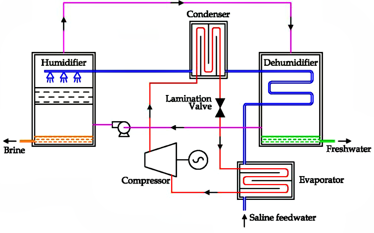
In the solution presented in Figure 25, the heat source from the condenser after the dehumidification unit is transferred to the brackish water. An alternative solution, shown in Figure 26, proposes transferring the heat source from the condenser to the air exiting the humidification unit. Instead of forced air circulation, a natural air circulation system is suggested, where the heat source is generated by a solar panel. In any case, HDH desalination remains a technology under investigation.

The majority of the Earth’s water is found in oceans and seas, making it non-potable and only suitable for consumption after applying separation techniques such as desalination to remove salts and minerals. As discussed, seawater desalination techniques encompass various chemical and physical methods that can produce fresh water. This versatility makes desalination adaptable to different needs and available resources. Historically, thermal solutions (such as MED and MSF) were the first adopted techniques. However, membrane-based technologies (primarily RO) are now rapidly expanding worldwide. Table 1 summarizes the advantages and disadvantages of the desalination systems described in this article.
Many of the technologies available in the market ensure products of varying quality and differ in terms of efficiency. However, based on studies, RO units have proven to be the best desalination technology due to their lower water production costs.
Additionally, the possibility of using electricity as an energy input, facilitated by commercial technologies such as photovoltaic panels and wind turbines, simplifies the integration with renewable energy sources.
As a result, it is possible to install small desalination units in small towns, with the hope that the use of renewable energy sources will expand, ensuring a sustainable approach to meeting freshwater demand.

[1] Sutherland, Kenneth S., and George Chase. Filters and filtration handbook. Elsevier, 2011.
[2] Hutten, Irwin M. Handbook of nonwoven filter media. Elsevier, 2007.
[3] Purchas, Derek, and Ken Sutherland, eds. Handbook of filter media. Elsevier, 2002.
[4] Curto, Domenico, Vincenzo Franzitta, and Andrea Guercio. “A review of the water desalination technologies.” Applied Sciences 11, no. 2 (2021): 670.
Author: Amin Forouzan

 Save the post
 Projects: