


Compressed air filtration is a key element in the production and utilization of compressed air. By removing contaminants such as solid particles, moisture, oil, and other pollutants from the air stream, it ensures access to high-quality compressed air with minimal contamination. One of the primary contaminants in compressed air is oil. The oil used in compressed air systems primarily serves purposes such as lubrication, sealing, and cooling of internal components and parts. Managing this oil must be based on maintaining clean oil within the compressor and minimizing its circulation throughout other system components. In fact, the combination of moisture from condensation in the compressed air, mixed with oil and solid pollutants, creates sludge that is detrimental to the performance of compressed air systems and equipment. Given the importance of compressed air quality, the removal of oil from the compressor’s output air is highly significant. This step is essential for maintaining the optimal performance of compressor-related equipment, preventing damage to downstream systems, reducing maintenance and repair costs, and improving the overall efficiency of compressor operations.
Air/oil separators use various mechanisms, such as centrifugal force and coalescing, to separate oil from air. Common types of these devices include separators with coalescing filter elements, centrifugal separators, and cyclonic separators. Given the significance of separators equipped with coalescing elements, the following sections will provide a detailed explanation of the operational mechanisms of this type of separator.
In the process of air compression by compressors, the residual oil in the compressed air is almost entirely removed using a cartridge element within a pressurized tank or a spin-on separator through the application of the coalescing effect. These separators effectively remove oil from the compressed air stream to protect the compressor’s components and other associated equipment. Typically, these separators are installed after the compressed air outlet. After separating the oil from the compressed air, the recovered oil is returned to the system. However, these separators generally do not eliminate all the oil from the compressed air, leaving behind some oil particles or aerosols. These remnants are subsequently removed in the next stages of compressed air filtration. Figure 2 illustrates an example of the placement of an air/oil separator in a screw compressor system.

Spin-on separators are a type of filter used in compressors. One of their main advantages is the ease and speed of replacement. The permanently installed components ensure reliable sealing. These filters typically consist of a housing and a cartridge element. Figure 3 presents a schematic of compressor air/oil filter separators and their structure.
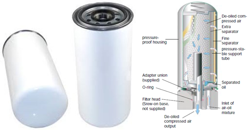
This type of oil separator consists of two main components: a chamber and a filter element. Oil separation in these separators generally occurs in two stages, aiming to recover lubricating oil before discharging the air at the required pressure. In the initial stage, gravitational settling is employed with the aid of reduced gas velocity, allowing some of the oil to collect in the filter tank. The subsequent stage involves passing the air stream through one or more multi-layered coalescing elements located within the separator chamber. The advantages of this type of separator include minimizing compressor oil loss, achieving high separation efficiency throughout the service life, low residual oil content, and minimal pressure drop.
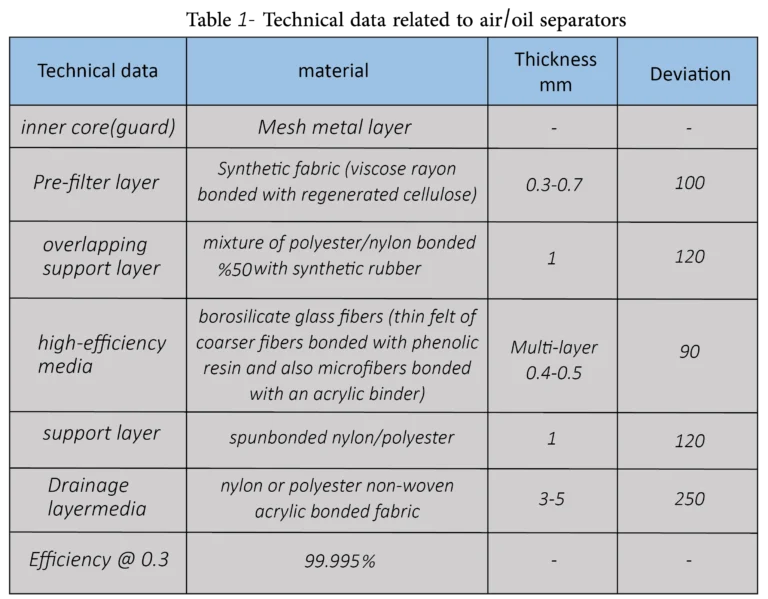
The coalescing elements in air/oil separators typically feature a multi-layered structure, where the arrangement of the layers depends on the flow direction within the filter. If the element operates from the inside out, the first layer acts as a pre-filtration layer, designed to capture larger particles. This layer often consists of fibrous fabrics such as synthetic materials with a thickness of 0.3–0.7 mm and a basis weight of approximately 100 g/m². Following this, there is a support layer, usually about 1 mm thick and weighing around 120 g/m², which may be composed of a polyester/nylon blend. The high-efficiency layers are predominantly made of fiberglass or borosilicate fibers with varying characteristics. These layers consist of a thin felt of coarser fibers bonded with phenolic resin or acrylic adhesive. Additional integrated support layers, often made from materials like nylon, provide structural stability to the fragile fiberglass media, ensuring resistance against frequent pressure fluctuations and cyclic loading. The separation process in these filters relies on the coalescing mechanism. The fundamental principle of coalescing is that two or more droplets merge to form larger droplets as they pass through the coalescing media. The operational mechanism of coalescing air/oil separators begins when oil-laden air enters the separator. Oil droplets of varying sizes collide with the fibers of the filter element and adhere to them, leading to the gradual coalescence of droplets. These larger oil droplets then drain into the lower chamber of the filter under the influence of gravity. These filters are typically capable of reducing the oil content in the compressed air stream to levels as low as 0.1 mg/m³ or less. After coalescing, the larger oil droplets are directed through a drainage layer, approximately 3–5 mm thick, made of materials such as nylon or nonwoven polyester fabrics, ensuring the rapid drainage of the separated liquid. Figure 4 illustrates the coalescing process of oil droplets on the fibers.
The entire assembly is mechanically locked into end caps with precise mechanical design, forming a highly efficient separator capable of removing particles as small as 0.3 micrometers with an efficiency exceeding 99.995%. The oil carryover from a typical compressor is usually less than 5 mg per cubic meter of air, enabling extended compressor service intervals.
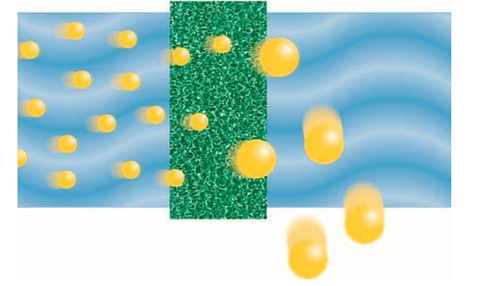
Table 2 presents some technical data related to air/oil separators based on scientific references.
Fiberglass fibers are commonly considered the ideal medium for coalescing droplets. Microfibers of fiberglass with diameters ranging from 0.5 to 0.75 micrometers typically deliver the best results as coalescing filter media. The depth of the fiber bed and the ratio of void space to fiber volume are critical for the effective performance of the coalescing filter. Additionally, borosilicate microfiber mesh without binders and with a three-dimensional layered structure is utilized to trap 99.99999% of all suspended oil and water droplets, as well as dust particles in compressed air, down to a size of 0.01 micrometers. These elements are chemically, biochemically, and biologically inert, offering significant advantages. It is important to note that the selection of the appropriate media and the layers in the structure of separators must be made based on the specific application and the requirements of the compressed air system.
The design of oil separators is generally based on three key parameters: separation efficiency, the volume and capacity of compressed air, and pressure drop. Changes in geometric design and inlet flow conditions can influence these three aspects and their interdependence. For compressor applications, the goal of optimal separator design is to achieve better oil separation efficiency within a smaller volume and with an acceptable pressure drop. Reducing the oil carryover in compressed air should ensure that the oil content remains within the range of 5 ppm.
The selection of a filter is based on the air capacity and filtration efficiency required. Although filter size and the grade of the element are determined separately, they are interrelated and cannot be considered independently. For standard systems operating at approximately 7.5 bar, filter selection begins with determining the maximum airflow at the filtration point, which corresponds to the free air consumption in standard liters per second before compression. Following this, the required air quality and the appropriate filter grade must be identified. Ultimately, a balance between performance requirements and economic considerations should be achieved.
To ensure the efficiency and quality of compressor oil separators, standardized ISO tests are used for evaluating air/oil separators in compressors. These standards provide specific guidelines and methodologies for assessing the performance of separators. One of the most important ISO standards relevant to air/oil separator testing is ISO 12500, which outlines procedures for evaluating the separation of oil contaminants in compressed air. Table 1 summarizes the components of this standard. These standard addresses two types of oil contaminants commonly found in compressed air: oil aerosols and oil vapor, ensuring comprehensive performance testing of separators across various operational scenarios.

When an air/oil separator fails, it can lead to a range of issues, including increased oil consumption, compressor failure, damage to downstream equipment and engines, and a reduction in overall efficiency. To prevent such problems, it is crucial to ensure that air/oil separators are regularly inspected and maintained to guarantee optimal performance and fuel efficiency.
One critical aspect to monitor during maintenance is the pressure drop across air/oil separators. Regarding the upkeep of coalescing elements, it is important to measure the pressure drop from the inlet to the outlet of the filter. Most output filters are equipped with pressure indicators in some form. Generally, when the pressure differential reaches 0.5 to 0.7 bar, the element needs replacement. Additionally, other indicators, parameters, and operational conditions must also be considered to estimate the appropriate replacement interval for these separators accurately.
Air/oil separators are essential components in any compressed air system. They play a critical role in preventing oil loss and ensuring that compressed air remains free of oil droplets and contaminants. These separators are also vital for protecting the internal components of compressors and downstream equipment. Whether utilizing a cartridge-type or spin-on air/oil separator, it is important to regularly inspect and maintain these devices to ensure proper functioning and provide the necessary protection for your compressed air system. Regular maintenance not only ensures optimal performance but also prolongs the life of the system and reduces operational costs.
[1] Sutherland, K. S., & Chase, G. (2011). Filters and filtration handbook. Elsevier.
[2] Hutten, I. M. (2007). Handbook of nonwoven filter media. Elsevier.
[3] https://blog.elgi.com/application-blog/benefits-of-an-air-oil-separator-in-an-air-compressor/
Author: Forough Khalili

 Save the post
 Projects: